|
Dynamic model-simulator of the steam boiler unit of the metallurgical combine in real time
Founded: January 2007
wget http://oscada.org/svn/trunk/OpenSCADA/data/ModelsDB/Boiler/Model.sql
sqlite3 -init Model.sql Model.db .exit
|
|
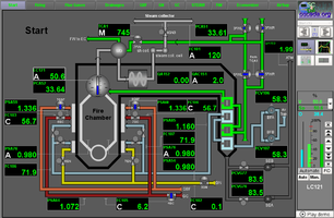
The modelling object of this project, for creation the full-scale real time dynamic simulator, is the multi-fuel steam boiler #9 of the Dnepr Metallurgical Combine (DMC). The distinctive feature of the boiler unit is the same multi-fuel nature and, as a consequence — features in optimal control of its load.
1 Purpose
Functionally, the development purpose is creation of the real time model-simulator of the multi-fuel boiler unit of the metallurgical combine.
Operational purpose of the development is:
- test of algorithms of the ASC TP control;
- test of the adequate operating of the SCADA-system;
- training of technical personnel;
- "live" demonstration of features and example of a project in the OpenSCADA SCADA-system, as the actual and finite goal, currently.
2 Development
In order to speed up the development, to use the experience of the previous developments, as well as to improve the technology and development tools of the complete dynamic real-time simulators, there was made the decision to build the simulator in the OpenSCADA environment. OpenSCADA has a powerful mechanism of user-side programming, as well as achievements to create a complete real-time dynamic simulators, which allow you to quickly create of large real-time dynamic simulators. For more information, see the concept-library of models of the technological devices.
Conceptually, complex simulators of the technological processes are divided and consist of three distinctly defined structural units, which in practical application are as clearly defined and can be used independently, after joint work, that is (from the bottom to the top):
- technological process — a real-time mathematical model that describes the work of a technological process in dynamics;
- Programming Logical Controller (PLC) — in fact, these are algorithms and regulators designed to control the stability of the technological process within the regimes defined by the technological regulations and these are reproduced by the complex simulator;
- SCADA — Supervisory Control And Data Acquisition system, which is a window to the technological process, receiving data from the PLC and issuing control actions.
2.1 The technological process
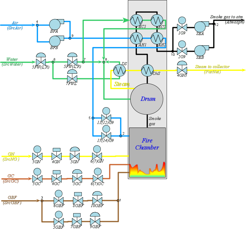
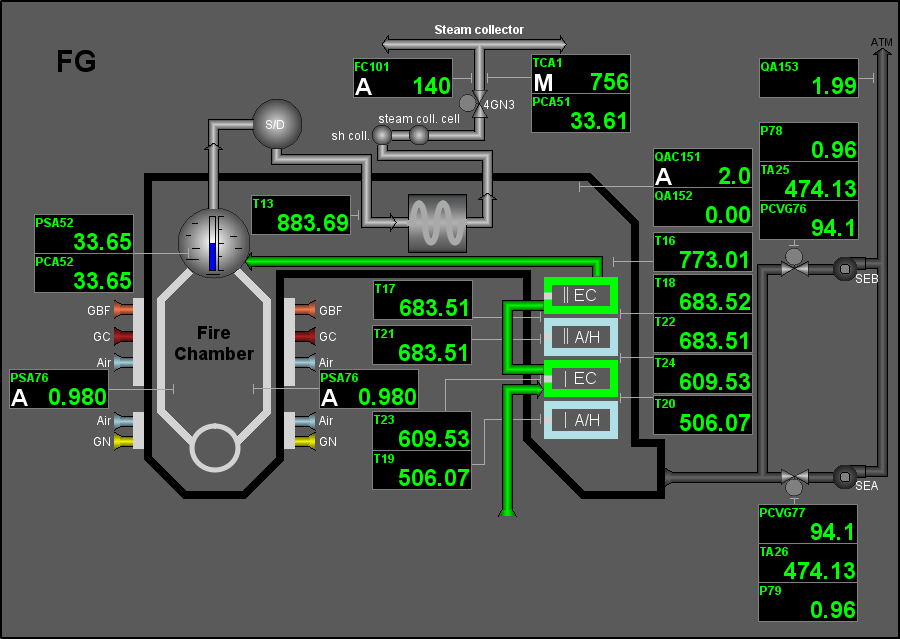
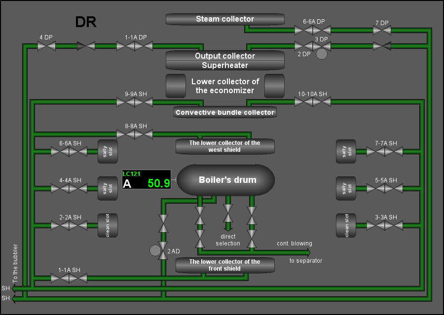
Before the creation of the boiler unit simulator the schematic diagram of its technological process was formed, based on the schematic diagram of the real technological process. The scheme is shown in Figure 1.
2.2 Simulating-modeling
To construct the simulator of the technological process, basing on the available devices models, the original principal diagram and the block calculator (BlockCalc) of OpenSCADA were directly used. The devices models of the technological scheme were appended to the block scheme in accordance with the principal one. Part of the blocks were been added for the auxiliary equipment, as well as for the flow nodes. Numbers of the node blocks on the principal diagram are indicated by numbers near the flow nodes.
The model is made as two block schemes of the block calculator. Content and properties of the block schemes are shown in Table 1.
Table 1. Block-scheme of the simulator
| Identifier | Name | Target | Execution period, seconds |
|---|---|---|---|
| boiler9 | DMC Boiler9 | Contains a simulator of the boiler unit #9 of the Dnepr Metallurgical Combine. | 0.005 |
| boiler9_cntr | DMC Boiler9 Controller | Contains a simulator of the control system of the boiler unit #9 of the Dnepr Metallurgical Combine. | 1 |
Table 2 shows the list of used device models, in accordance with the principle diagram.
Table 2. Models of the used technological devices
| Model of the technological device | Devices (blocks of the simulator) |
|---|---|
| The library "Technological devices" | |
| Boiler: barrel (boilerBarrel) | boiler9.Drum |
| Boiler: burner (boilerBurner) | boiler9.FireChamber |
| Gas compressor (compressor) | boiler9.SEA, boiler9.SEB, boiler9.BFA, boiler9.BFB |
| Heat exchanger (heatExch) | boiler9.OhS, boiler9.AH1, boiler9.AH2, boiler9.DS, boiler9.EC1, boiler9.EC2 |
| Valve (klap) | boiler9.3FW, boiler9.5FW, boiler9.7FW, boiler9.5GBF, boiler9.6GBF, boiler9.7GBF, boiler9.8GBF, boiler9.9GBF, boiler9.10GBF, boiler9.3GC, boiler9.4GC, boiler9.6GC, boiler9.5GC, boiler9.3GN, boiler9.4GN, boiler9.5GN, boiler9.6GN, boiler9.4GN3, boiler9.1G, boiler9.2G, boiler9.11G, boiler9.13G |
| Network (loading) (net) | boiler9.ParNet, boiler9.Atmosph |
| Pipe 1->2 (pipe1_2) | boiler9.Node3, boiler9.Node5, boiler9.Node6, boiler9.Node7, boiler9.Node10 |
| Pipe 2->1 (pipe2_1) | boiler9.Node1, boiler9.Node2, boiler9.Node9, boiler9.Node12 |
| Pipe 3->1 (pipe3_1) | boiler9.Node8 |
| Source (pressure) (src_press) | boiler9.SrcGBF, boiler9.SrcGC, boiler9.SrcWater, boiler9.SrcNG, boiler9.SrcAir |
| The library "Complex1 functions" | |
| PID regulator (pid) | boiler9_cntr.TCA1, boiler9_cntr.F_air_gas, boiler9_cntr.QAC151, boiler9_cntr.LC121, boiler9_cntr.PCA51, boiler9_cntr.FC101, boiler9_cntr.FC102, boiler9_cntr.FC103, boiler9_cntr.FC104, boiler9_cntr.FC105, boiler9_cntr.PSA76 |
| The library "Boiler К9" (JavaLikeCalc.lib_boiler9, with this project) | |
| Divider (Divider) | boiler9_cntr.Air_Gas |
| Total fuel flow in the boiler (Fsum) | boiler9_cntr.Fsum |
| Inversion (Inversion) | boiler9_cntr.5FW_inv |
Through the usage of the apparatus models library and the dynamic models building conception it was obtained the dynamic simulator, from which you can get the parameters at any point of the principal diagram both for the study and for testing the control algorithms.
For information about the technological process the parameters were created (Table 3), which provide data from selected nodes of the simulator.
Table 3. Parameters of the technological process
| Cipher | Description | Properties | Source |
|---|---|---|---|
| DMC Boiler9 (BlockCalc.boiler9) | |||
| LC121 | Water level in the boiler drum | Drum.Lo | |
| LСA122, LSA124 | Level of water in the clean slot of the drum, in the right | %, (0;100), Precision 0 | Drum.Lo |
| LSA123 | Level of water in the clean slot of the drum, in the left | %, (0;100), Precision 0 | Drum.Lo |
| LCVG121 | 3FWL position | %, (0;100), Precision 0 | 3FW.l_kl1 |
| LCVG122 | 3FWR position | %, (0;100), Precision 0 | 3FW.l_kl2 |
| G_11SH | 11G position | 11G.l_kl1 | |
| G_12SH | 12G position | 11G.l_kl2 | |
| G_13SH | 13G position | 13G.l_kl1 | |
| G_14SH | 14G position | 13G.l_kl2 | |
| l_5FW | 5FW(1) position | 5FW.l_kl1 | |
| l_5FW_2 | 5FW(2) position | 5FW.l_kl2 | |
| l_7FW | 7FW position | 7FW.l_kl1 | |
| l_4GN | 4GN position | 4GN.l_kl1 | |
| l_5GN | 5GN position | 5GN.l_kl1 | |
| l_7GBF | 7GBF position | 7GBF.l_kl1 | |
| l_8GBF | 8GBF position | 8GBF.l_kl1 | |
| FCVG102 | 5GN position | 5GN.l_kl1 | |
| FCVG103 | 7GBF position | 7GBF.l_kl1 | |
| FCVG104 | 8GBF position | 8GBF.l_kl1 | |
| FCVG105 | 4GC position | 4GC.l_kl1 | |
| TCVG1_1 | 7FW position | 7FW.l_kl1 | |
| TCVG1_2 | 5FWL position | 5FW.l_kl1 | |
| PCVG76 | SEA productivity | rpm, (0;100), Precision 1 | SEA.N |
| PCVG77 | SEB productivity | rpm, (0;100), Precision 1 | SEB.N |
| FCV106 | BFA productivity | rpm, (0;100), Precision 1 | BFA.N |
| FCV107 | BFB productivity | rpm, (0;100), Precision 1 | BFB.N |
| PCA51 | Steam pressure after the MSV | at, (0;50), Precision 2 | 4GN3.Po |
| PSA52 | Steam pressure in the boiler drum | at, (0;40), Precision 2 | Drum.Po1 |
| PCA52 | Steam pressure in the boiler drum | at, (0;50), Precision 2 | Drum.Po1 |
| PSA52_1 | Steam pressure in the boiler drum | at, (0;40), Precision 2 | Drum.Po1 |
| PSA53 | GN pressure before the regulating valve | at, (0;40), Precision 2 | 3GN.Po |
| PSA53_1 | GN pressure before the diaphragm | at, (0;40), Precision 2 | 3GN.Po |
| PSA53_2 | GN pressure before the diaphragm | at, (0;40), Precision 2 | 3GN.Po |
| PSA54 | GN pressure after the regulating valve | at, (0;1.5), Precision 3 | 5GN.Po |
| PA55 | GN pressure before the left burner | at, (0;40), Precision 2 | 6GN.Po |
| PA56 | GN pressure before the right burner | at, (0;40), Precision 2 | 6GN.Po |
| PSA57_1, PSA57_2 | GBF pressure on the general pipeline | at, (0;2), Precision 2 | Node3.Pi |
| PSA59 | GBF pressure after valve on the left gas pipeline | at, (1;2), Precision 3 | 10GBF.Po |
| PSA60 | GBF pressure after valve on the right gas pipeline | at, (1;2), Precision 3 | 9GBF.Po |
| P61 | GBF pressure before the left burner | at, (0;1.6), Precision 2 | 9GBF.Po |
| P62 | GBF pressure before the right burner | at, (0;1.6), Precision 2 | 10GBF.Po |
| PSA63_1 | GC pressure after 5GC | at, (0;2), Precision 2 | 5GC.Po |
| PSA63_2 | GC pressure after 3GC | at, (0;2), Precision 2 | 3GC.Po |
| PSA64 | GC pressure after the regulating valve | at, (0;2), Precision 3 | 4GC.Po |
| P65 | GC pressure before the left burner | at, (0;1.6), Precision 2 | 6GC.Po |
| P66 | GC pressure before the right burner | at, (0;1.6), Precision 2 | 6GC.Po |
| P67 | Air pressure before the first stage of the A/H to the left | at, (0;1.2), Precision 2 | Node9.Po |
| P68 | Air pressure before the first stage of the A/H to the right | at, (0;1.2), Precision 2 | Node9.Po |
| PSA70 | Air pressure after the second stage of the A/H | at, (0;1.2), Precision 2 | AH2.Po2 |
| PSA71 | Air pressure after the second stage of the A/H | at, (0;1.2), Precision 2 | AH2.Po2 |
| P72 | Air pressure in the upper tier of the left burner | at, (0;1.2), Precision 2 | Node2.Po |
| P73, PSA73 | Air pressure in the upper tier of the right burner | at, (0;1.16), Precision 2 | Node2.Po |
| P74 | Air pressure on the lower tier of the left burner | at, (0;1.16), Precision 2 | Node2.Po |
| P75, PSA75 | Air pressure on the lower tier of the right burner | at, (0;1.16), Precision 2 | Node2.Po |
| PCSA76 | Vacuum in the fire chamber on the left | at, (0.9;1), Precision 3 | FireChamber.Po |
| PCSA77 | Vacuum in the fire chamber on the right | at, (0.9;1), Precision 3 | FireChamber.Po |
| P78 | Vacuum in the "SE-A" front | at, (0.9;1), Precision 2 | 1G.Po |
| P79 | Vacuum in the "SE-B" front | at, (0.9;1), Precision 2 | 2G.Po |
| PSA80 | FW pressure on the left feeding line | at, (0;60), Precision 2 | SrcWater.Po |
| PSA81 | FW pressure on the right feeding line | at, (0;60), Precision 2 | SrcWater.Po |
| PSA85 | Air pressure after the A/H | at, (0;2), Precision 3 | AH2.Po2 |
| P103 | GBF pressure on the diaphragm on the left | at, (0;2), Precision 2 | Node3.Po2 |
| P104 | GBF pressure on the diaphragm on the right | at, (0;2), Precision 2 | Node3.Po1 |
| Src_GN_Pi | Input pressure at the source of GN | SrcNG.Pi | |
| P_GN_S | GN pressure after the source | SrcNG.Po | |
| P_4GN | GN pressure after 4GN | 4GN.Po | |
| l_3FW_1 | 3FW(1) position | 3FW.l_kl1 | |
| l_3GN | 3GN position | 3GN.l_kl1 | |
| l_6GN_1 | 6GN_1 position | 6GN.l_kl1 | |
| l_6GN_2 | 6GN_2 position | 6GN.l_kl2 | |
| l_5GC | 5GC position | 5GC.l_kl1 | |
| Pdrum | Pressure in the boiler drum | Drum.Po1 | |
| TCA1 | Steam temperature after MSV | 4GN3.To | |
| F_3FW | Water flow after 3FW | 3FW.Fo | |
| F_5FW | Water flow after 5FW | 5FW.Fo | |
| F_7FW | Water flow after 7FW | 7FW.Fo | |
| Fdrum | Water flow into the drum | Drum.Fi1 | |
| F_Node8 | Water flow after Node8 | Node8.Fo | |
| FC101 | Steam flow from the boiler | t/h, (0;100), Precision 2 | 4GN3.Fo |
| FC102 | Natural gas flow | 3GN.Fo | |
| FC102_0 | Natural gas flow after the source | SrcNG.Fo | |
| FC102_1 | Natural gas flow after 4GN | 4GN.Fo | |
| FC102_2 | Natural gas flow after 5GN | 5GN.Fo | |
| FC102_3 | Natural gas flow after 6GN | 6GN.Fo | |
| FC103 | GBF flow on the gas pipeline left | 5GBF.Fi | |
| FC104 | GBF flow on the gas pipeline right | 6GBF.Fi | |
| FC105 | Coke gas flow of after 5GC | 5GC.Fo | |
| FC106 | Air flow to the left burner | t/h, (0;100), Precision 1 | Node2.Fi1 |
| FC107 | Air flow to the right burner | t/h, (0;100), Precision 1 | Node2.Fi2 |
| FA108 | Air-superheater flow on the right feeding line | t/h, (0;200), Precision 2 | SrcWater.Fo |
| F109 | Water flow for the thermostat | t/h, (0;200), Precision 2 | 7FW.Fo |
| FA110 | Air-superheater flow on the left feeding line | t/h, (0;200), Precision 2 | SrcWater.Fo |
| QA151 | Oxygen content in FG after the superheater | %, (0;20), Precision 2 | FireChamber.O2 |
| QA152 | CO content in FG after the superheater | %, (0;20), Precision 2 | FireChamber.CO |
| QA153 | Oxygen content in the exhaust FG | %, (0;20), Precision 2 | FireChamber.O2 |
| T2 | Natural gas temperature | deg.K, (223;323), Precision 2 | 3GN.To |
| T3 | GBF temperature | deg.K, (273;373), Precision 2 | 5GBF.Ti |
| T5 | GC temperature on the boiler | deg.K, (273;373), Precision 2 | 4GC.To |
| T7 | Air temperature after the second stage of the A/H on the left | deg.K, (273;773), Precision 2 | AH2.To2 |
| T8 | Air temperature after the second stage of the A/H on the right | deg.K, (273;773), Precision 2 | AH2.To2 |
| T13 | FG temperature before the superheater on the left | deg.K, (273;1027), Precision 2 | Drum.To2 |
| T14 | FG temperature before the superheater on the right | deg.K, (273;1027), Precision 2 | Drum.To2 |
| T15 | FG temperature before the second stage of the economizer on the left | deg.K, (273;873), Precision 2 | OhS.To1 |
| T16 | FG temperature before the second stage of the economizer on the right | deg.K, (273;873), Precision 2 | OhS.To1 |
| T17 | FG temperature after the second stage of the economizer on the left | deg.K, (273;873), Precision 2 | EC2.To1 |
| T18 | FG temperature after the secind stage of the economizer on the right | deg.K, (273;873), Precision 2 | EC2.To1 |
| T19 | FG temperature before the first stage of the A/H on the left | deg.K, (273;873), Precision 2 | EC1.To1 |
| T20 | FG temperature before the first stage of the A/H on the right | deg.K, (273;873), Precision 2 | EC1.To1 |
| T21 | FG temperature before the second stage of the A/H on the left | deg.K, (273;873), Precision 2 | EC2.To1 |
| T22 | FG temperature before the second stage of the A/H on the right | deg.K, (273;873), Precision 2 | EC2.To1 |
| T23 | FG temperature before the first stage of the economizer on the left | deg.K, (273;873), Precision 2 | AH2.To1 |
| T24 | FG temperature before the first stage of the economizer on the right | deg.K, (273;873), Precision 2 | AH2.To1 |
| TA25 | FG temperature before the "SE-A" | deg.K, (273;673), Precision 2 | 1G.To |
| TA26 | FG temperature before the "SE-B" | deg.K, (273;673), Precision 2 | 2G.To |
| T35 | Temperature of the A/H on the left feeding line | deg.K, (273;473), Precision 2 | 3FW.To |
| T36 | Temperature of the A/H on the right feeding line | deg.K, (273;473), Precision 2 | 3FW.To |
| T37 | Water temperature after the economizer on the left | deg.K, (273;673), Precision 2 | EC2.To2 |
| T38 | Water temperature after the economizer on the right | deg.K, (273;673), Precision 2 | EC2.To2 |
| DMC Boiler9 Controller (BlockCalc.boiler9_cntr) | |||
| TCA1 | Steam temperature at the output | K, (273;800), Precision 0 | TCA1.* |
| QAC151 | Percentage of oxygen in the flue gases | %, (0;15), Precision 1 | QAC151.* |
| LC121 | Level in the boiler drum | %, (0;100), Precision 1 | LC121.* |
| 5FW | %, (0;100), Precision 1 | 5FW_inv.OVar | |
| FC101 | Steam flow from the boiler | t/h, (0;150), Precision 0 | FC101.* |
| FC102 | Natural gas flow | t/h, (0;6), Precision 1 | FC102.* |
| FC103 | Blast furnace gas flow on the left gas pipeline | t/h, (0;70), Precision 1 | FC103.* |
| FC104 | Blast furnace gas flow on the right gas pipeline | t/h, (0;70), Precision 1 | FC104.* |
| FC105 | Coke oven gas flow | t/h, (0;10), Precision 1 | FC105.* |
| PSA76 | Vacuum in the fire chamber | at, (0.9;1), Precision 3 | PSA76.* |
2.3 Regulation
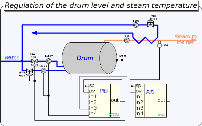
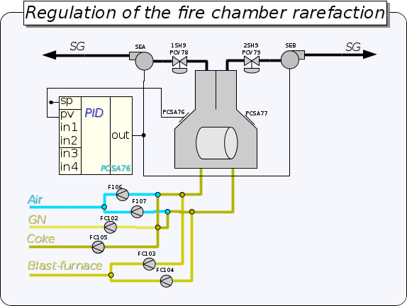
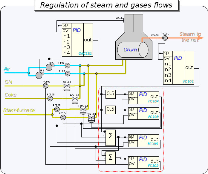
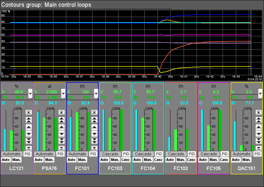
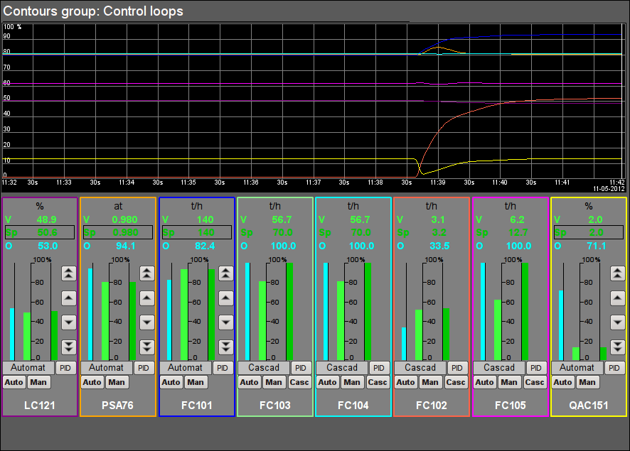
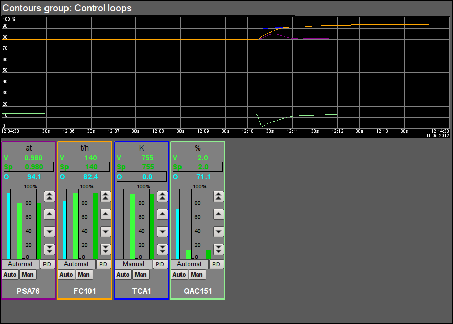
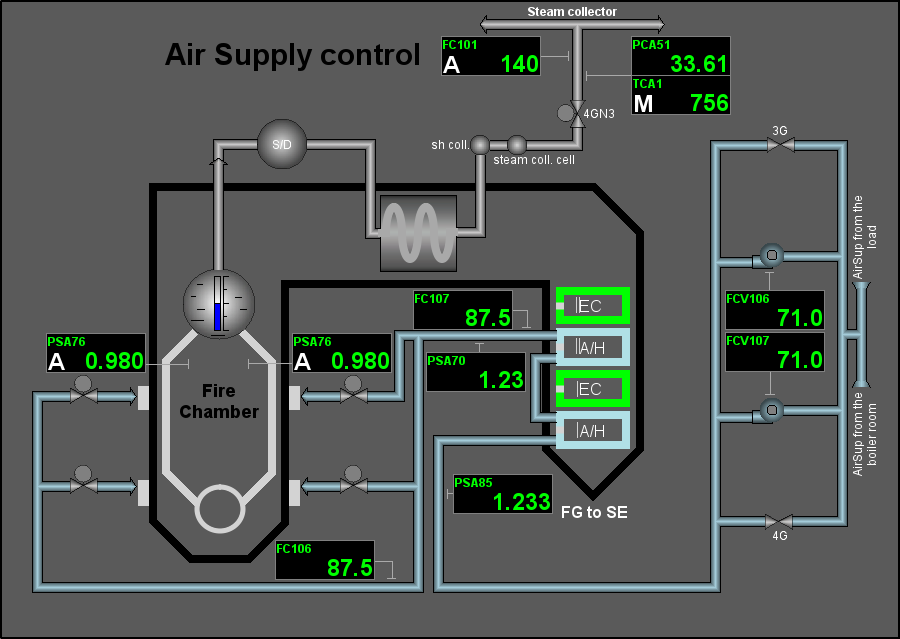
The dynamic model-simulator itself may be unstable without control. For example, the parameter of the drum level does not have the self-regulation and goes to extremes in the case of the balance absence in the control parameters, which is typical of a pure integral. For this reason, as well as to create a self-sufficient simulator capable of operating autonomously and without the PLC as a regulator, an object was created for the regulators controller for the boiler simulator in accordance with the regulation schemes in Figure 2-4.
3 User interface
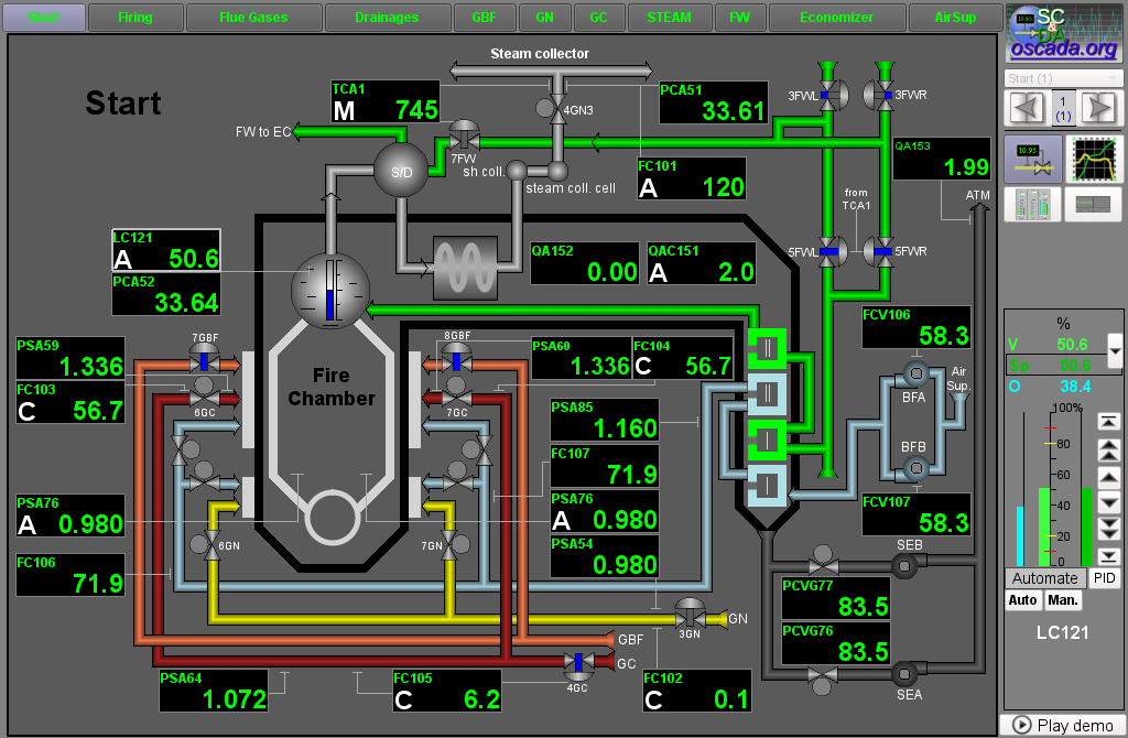
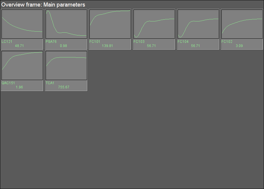
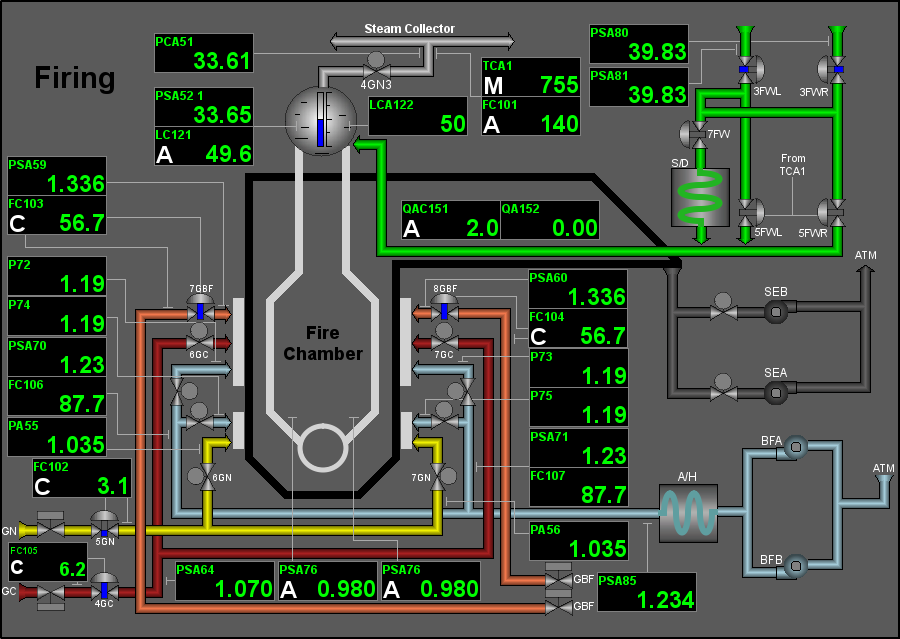
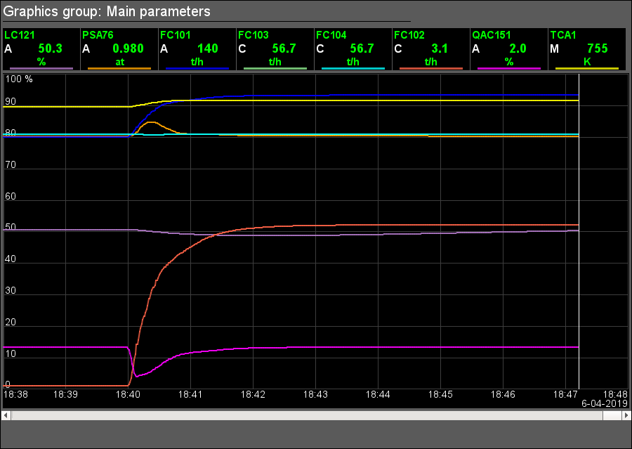
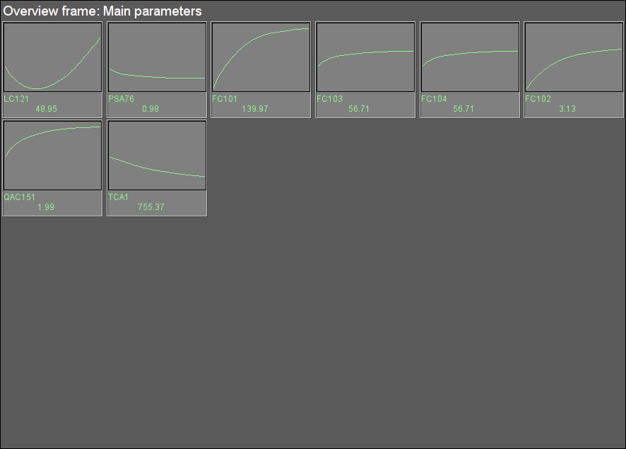
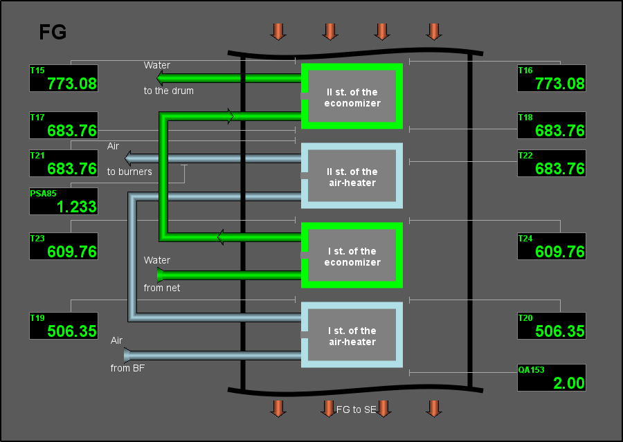
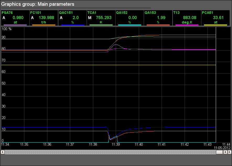
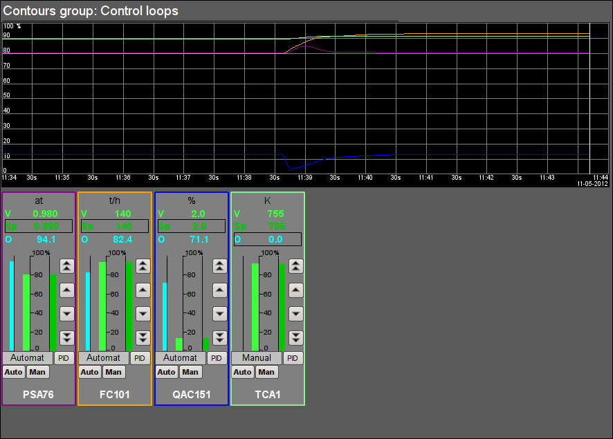
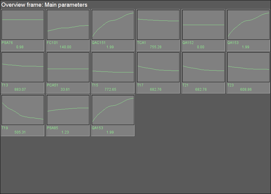
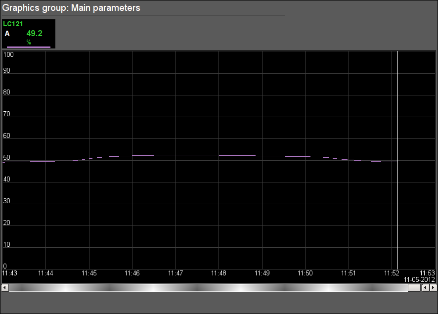
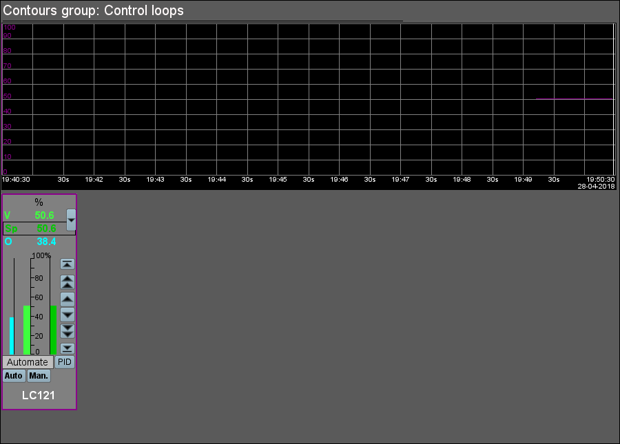
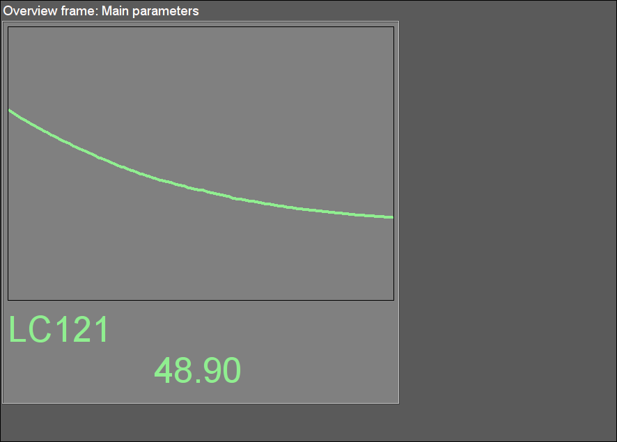
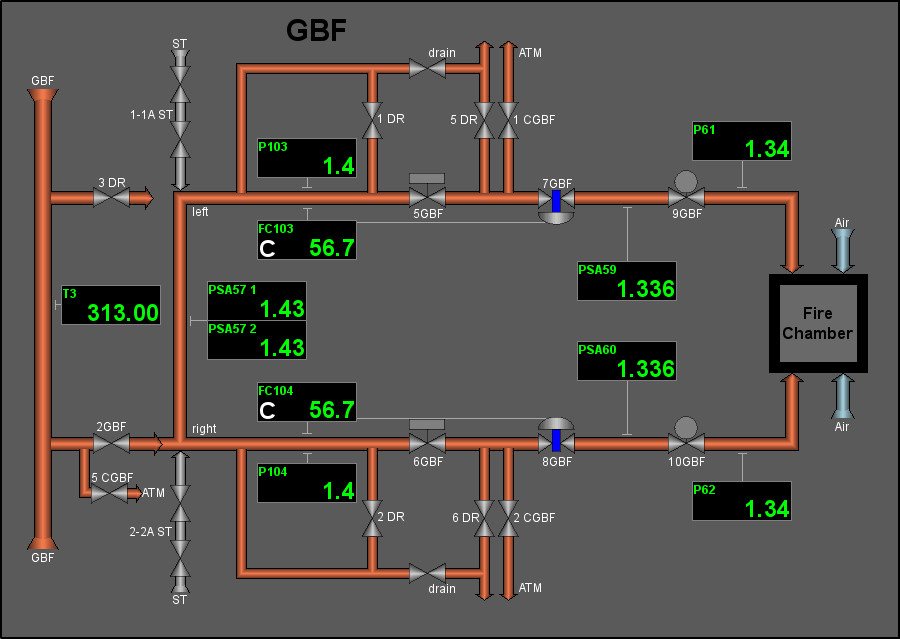
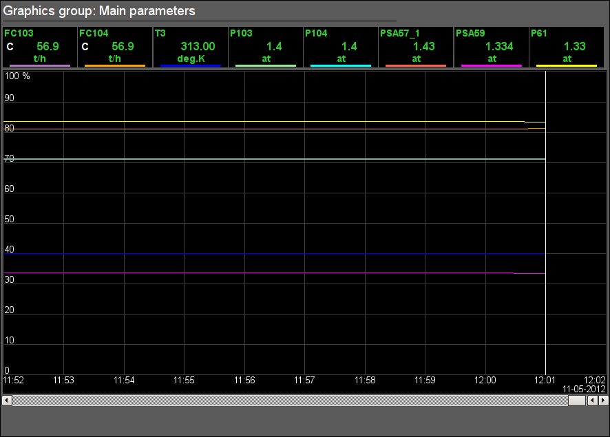
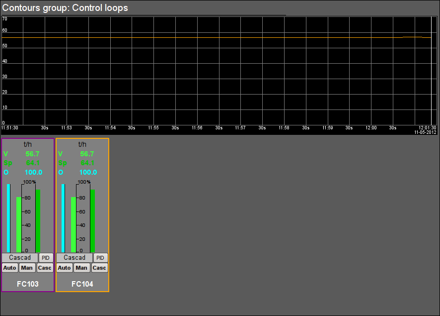
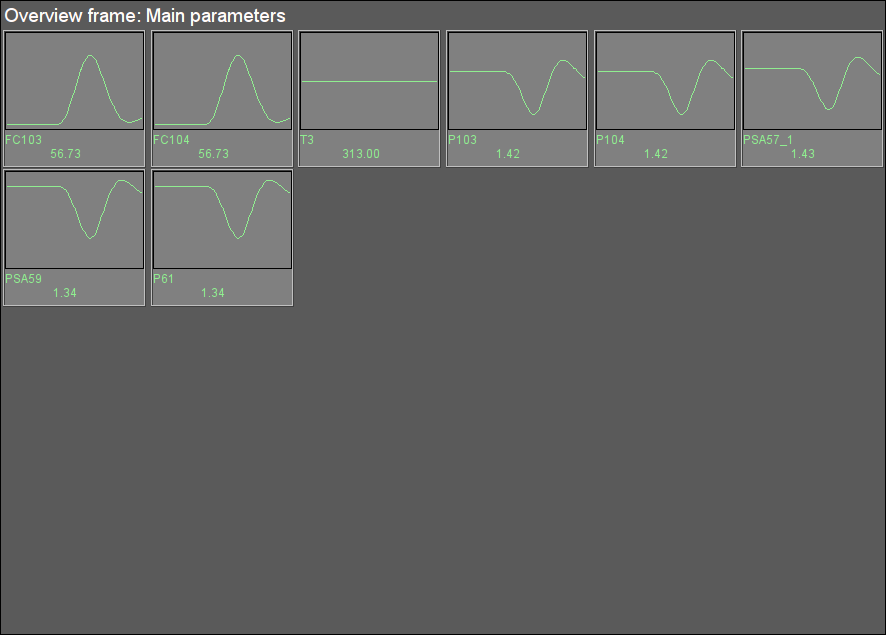
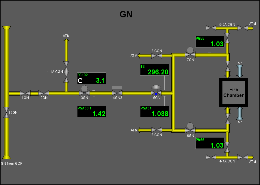
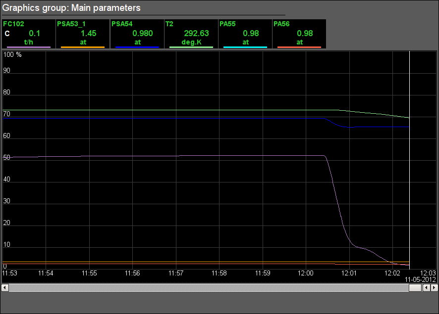
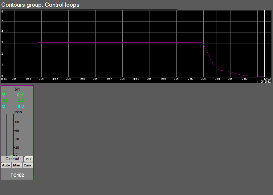
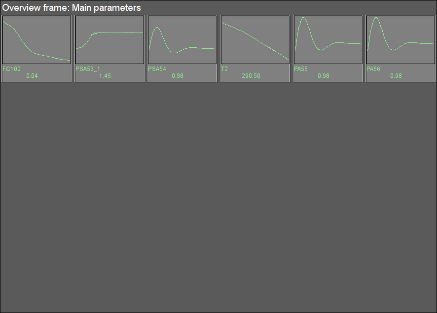
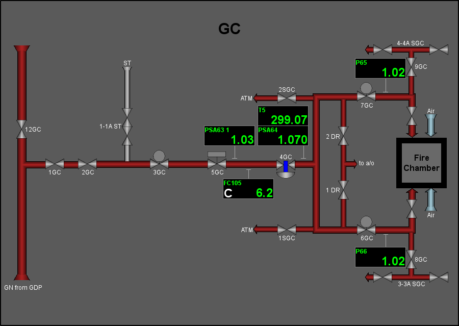
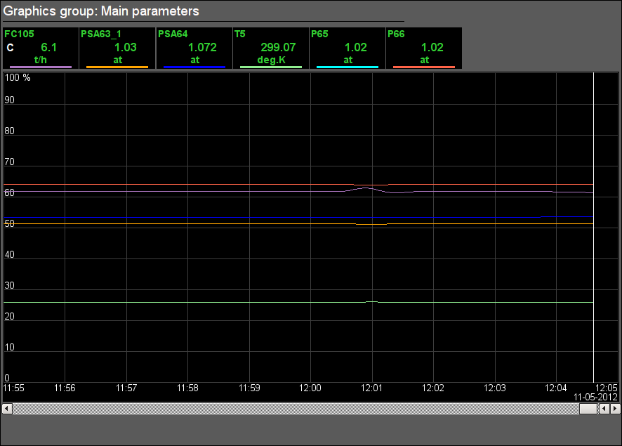
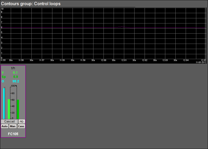
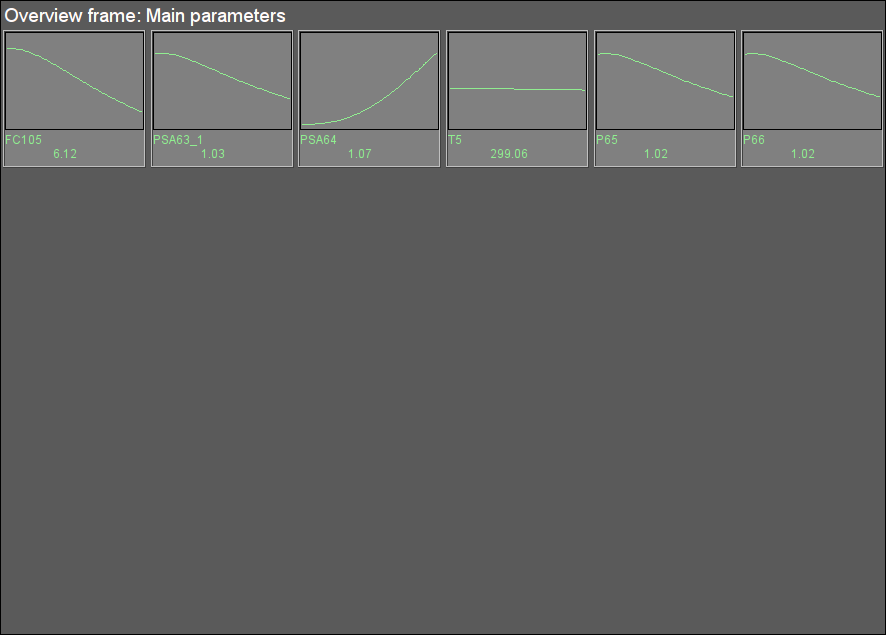
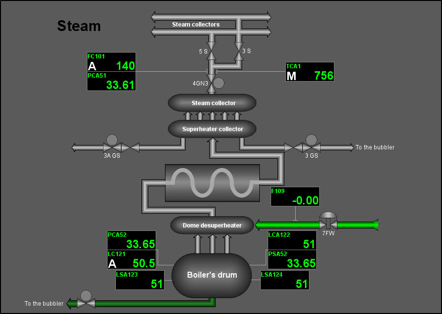
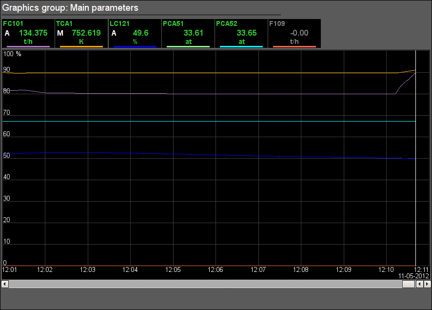
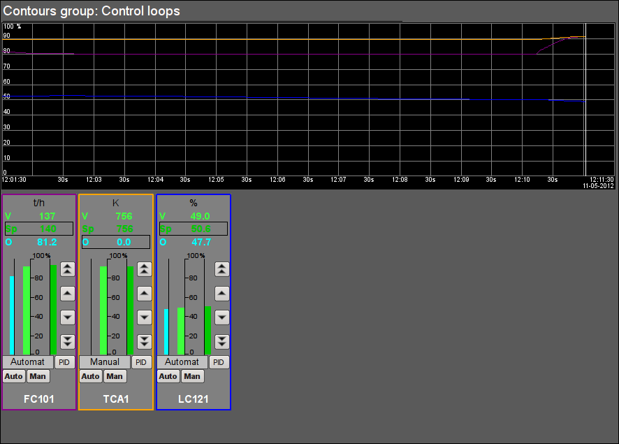
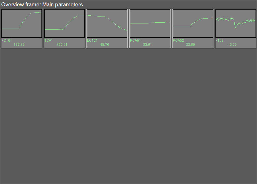
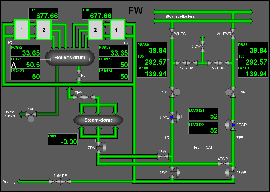
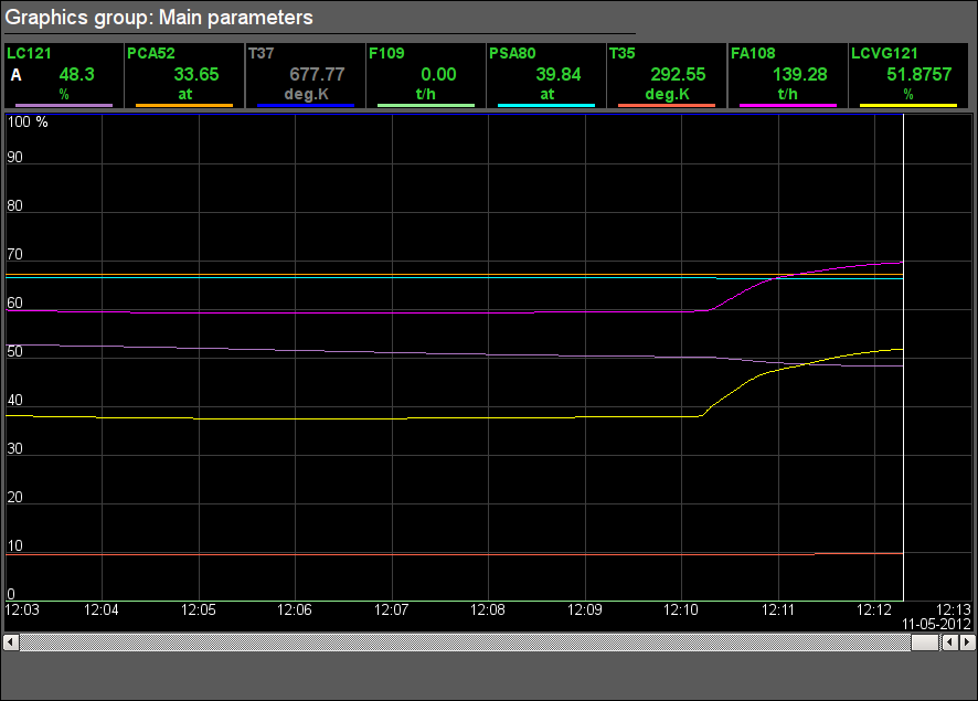
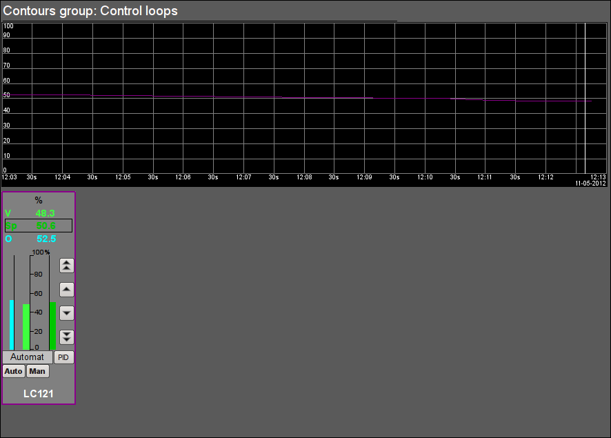
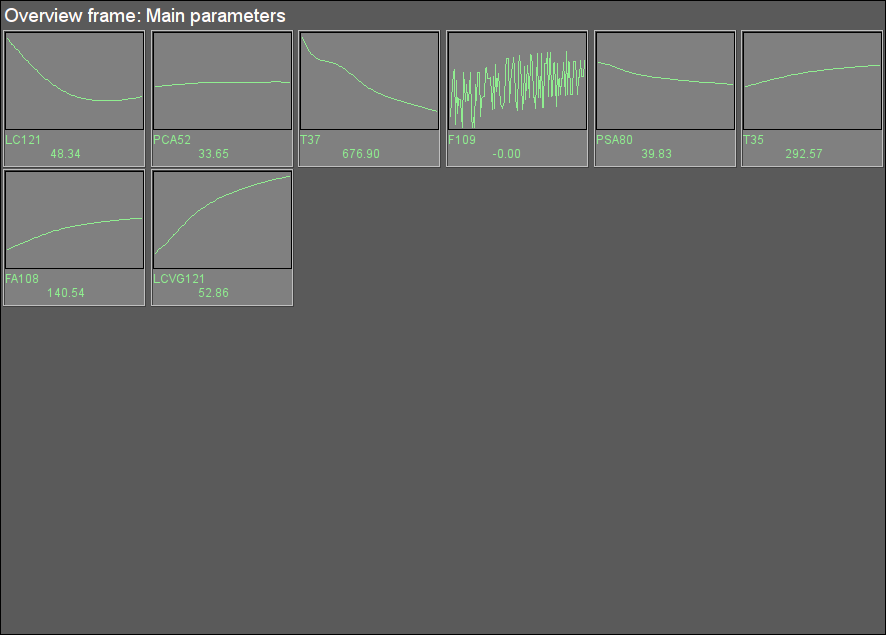
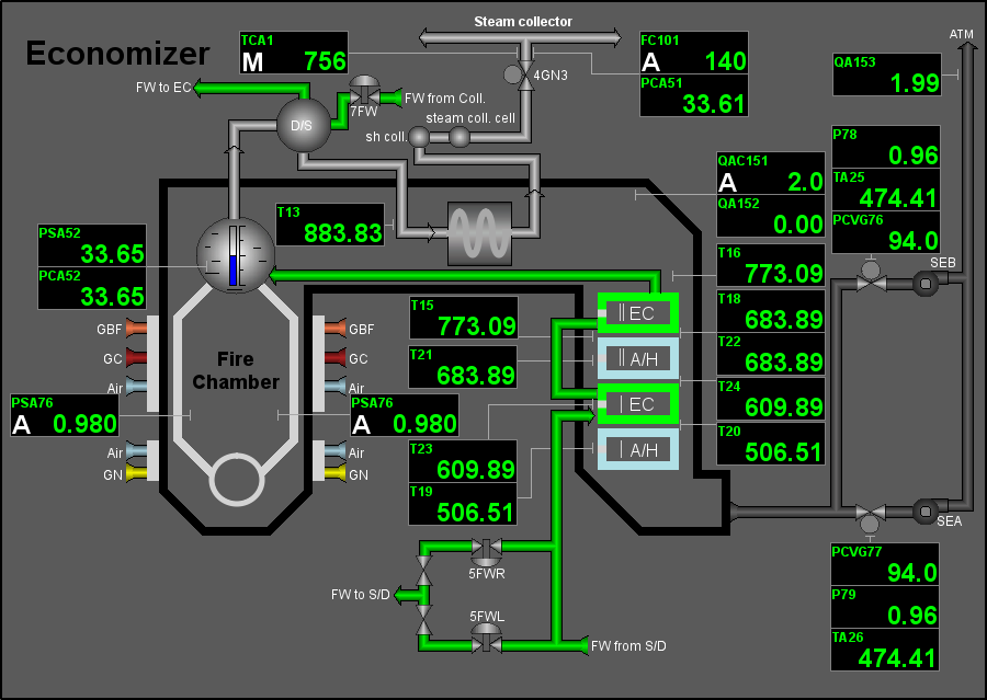
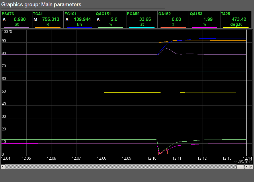
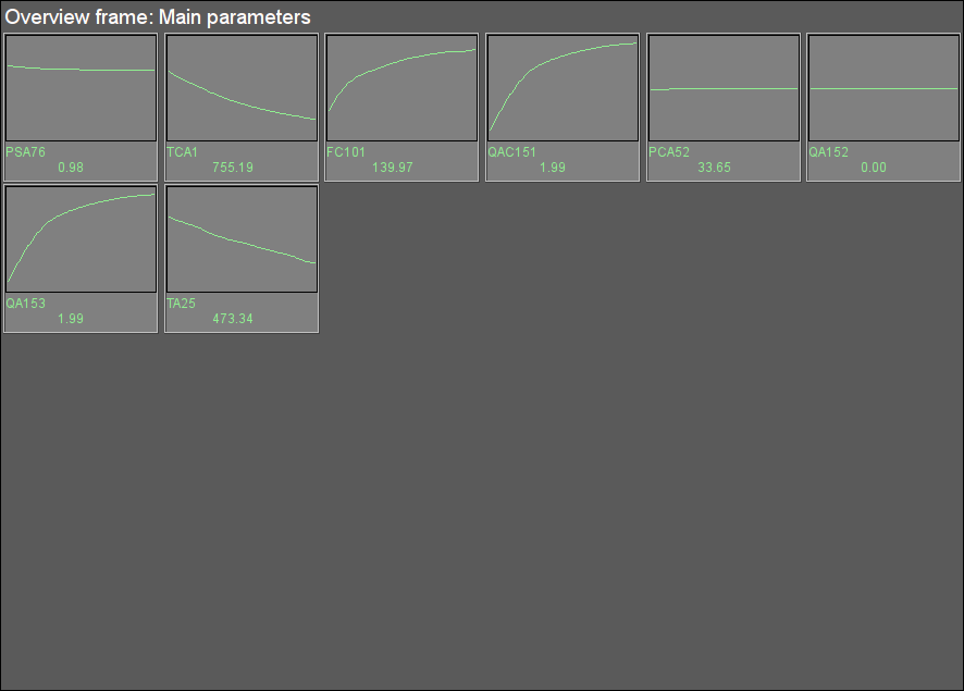
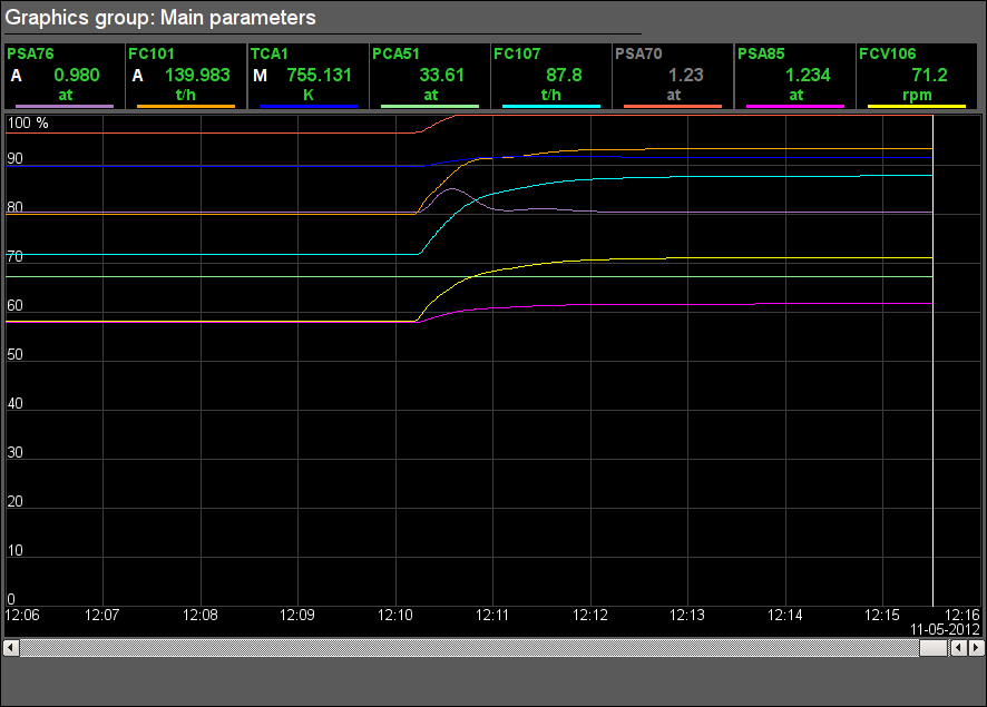
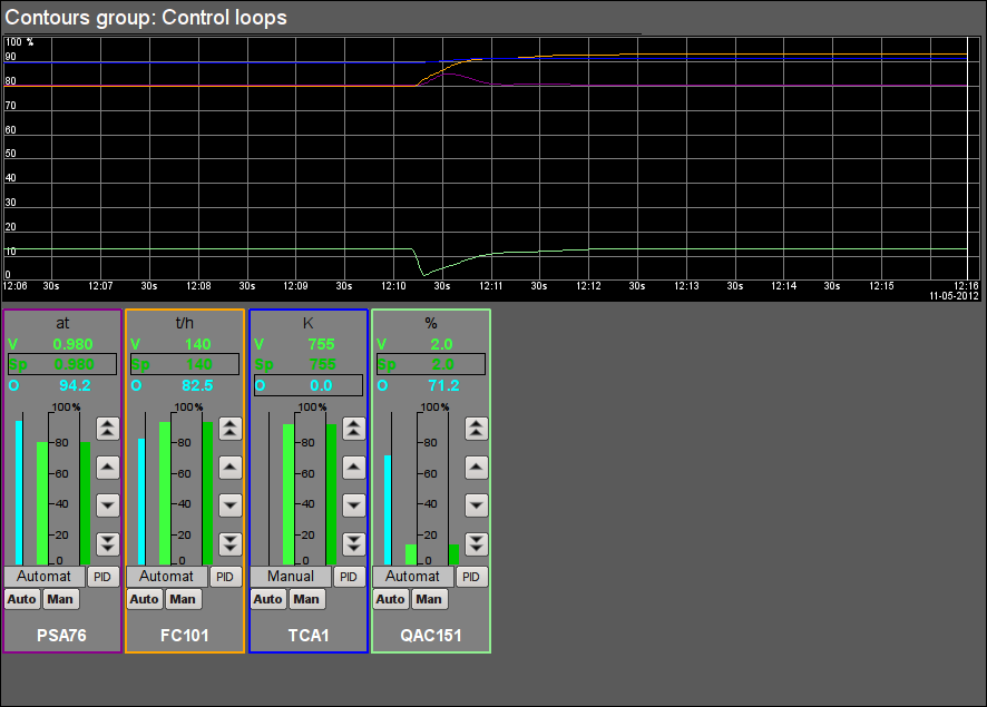
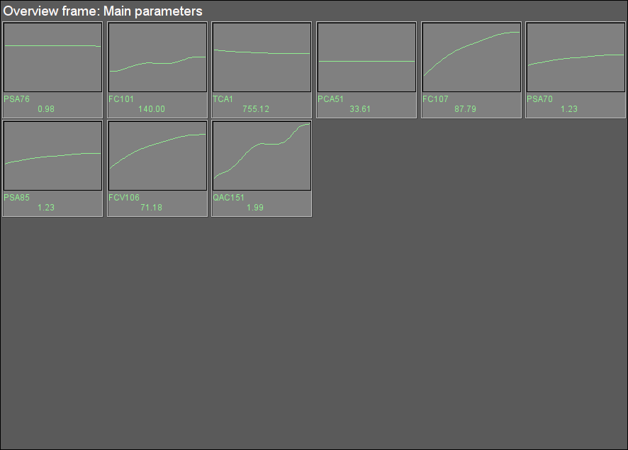
User interface of the simulator contains eleven signal objects (Fig.5). Each object contains several mnemonic cadres, graphic groups, contour groups and overview groups.
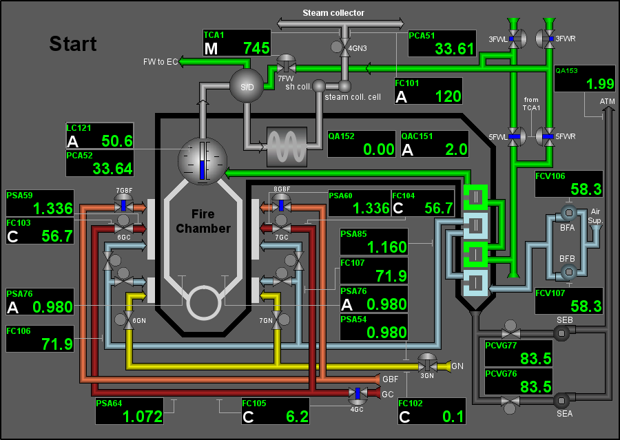
3.1 Signal object "Start"
3.2 Signal object "Firing"
3.3 Signal object "Flue Gases"
3.4 Signal object "Drainages"
3.5 Signal object "GBF"
3.6 Signal object "GN"
3.7 Signal object "GC"
3.8 Signal object "STEAM"
3.9 Signal object "FW"
3.10 Signal object "Economizer"
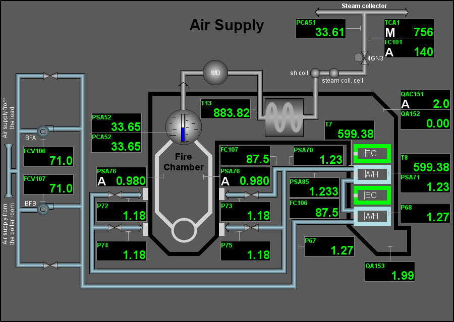
3.11 Signal object "AirSup"
4 Results
The development result is complete dynamic simulator of the technological process of the multifuel steam boiler unit for the high pressure and high productivity. This simulator is available in three languages and is included to the OpenSCADA distributives to demonstrate the functions and features.
The model envisages the ability to control the TP on behalf of the operator, including operations:
- control of regulators:
- changing the regulator mode: "Automate", "Manual" and "Cascade";
- setting the desirable setpoint value or manual output of the executive mechanism;
- configuration the PID-regulator parameters.
In general, in the control scheme, the following regulators are fully involved:
- LC121 — level in the boiler drum;
- PSA76 — vacuum in the boiler furnace;
- FC101 — steam flow from the boiler;
- FC102 — natural gas flow;
- FC103, FC104 — flow of the blast furnace gas;
- FC105 — flow of the coke oven gas;
- QAC151 — percentage of oxygen in the flue gases;
- TCA1 — steam temperature at the output.
In an applied sense the model let us to work out the control algorithms of the multi fuel supply.
Resource intensity of the simulator in whole, to the CPU Athlon 64 3000+ (2000MHz) is 22%, to the CPU 800 MHz is 70%.
