|
Dynamic model-simulator of the Gas-lifting compressor station in real time
Founded: January 2006
wget http://oscada.org/svn/trunk/OpenSCADA/data/ModelsDB/AGLKS/Model.sql
sqlite3 -init Model.sql Model.db .exit
|
|
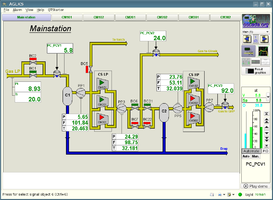
Anastasievska GLKS (AGLKS) is a technological process designed for two-stage gas compression of gas fields. For this purpose GLKS is provided with six centrifugal compressors: three compressor for low and high pressure part, thus providing redundancy and allowing the parallel operation.
Contents
1 Purpose
Functionally, the development purpose is creation of the Gas-lifting compressor station in real time.
Operational purpose of the development is:
- test of algorithms of the ASC TP control, especially it is the anti-surging algorithms;
- test of the adequate operating of the SCADA-system;
- training of technical personnel;
- "live" demonstration of features and example of a project in the OpenSCADA SCADA-system, as the actual and finite goal, currently.
2 Development
Primarily this project and the simulator-model were created to test the control algorithms of GLKS, especially anti-surging algorithms. It was supposed to launch the simulator on a single-board computer with MOD and interaction with the controller of controlling the technological process. In development of the model it was used library of the technological apparatuses of OpenSCADA. Subsequently, the TP simulator of the compressor station has grown into an autonomous system which is used in the OpenSCADA project as an example, a demonstration of the features and capabilities. The text values of the simulator are available in three languages: English, Ukrainian and mRussian.
Conceptually, complex simulators of the technological processes are divided and consist of three distinctly defined structural units, which in practical application are as clearly defined and can be used independently, after joint work, that is (from the bottom to the top):
- technological process — a real-time mathematical model that describes the work of a technological process in dynamics;
- Programming Logical Controller (PLC) — in fact, these are algorithms and regulators designed to control the stability of the technological process within the regimes defined by the technological regulations and these are reproduced by the complex simulator;
- SCADA — Supervisory Control And Data Acquisition system, which is a window to the technological process, receiving data from the PLC and issuing control actions.
2.1 The technological process
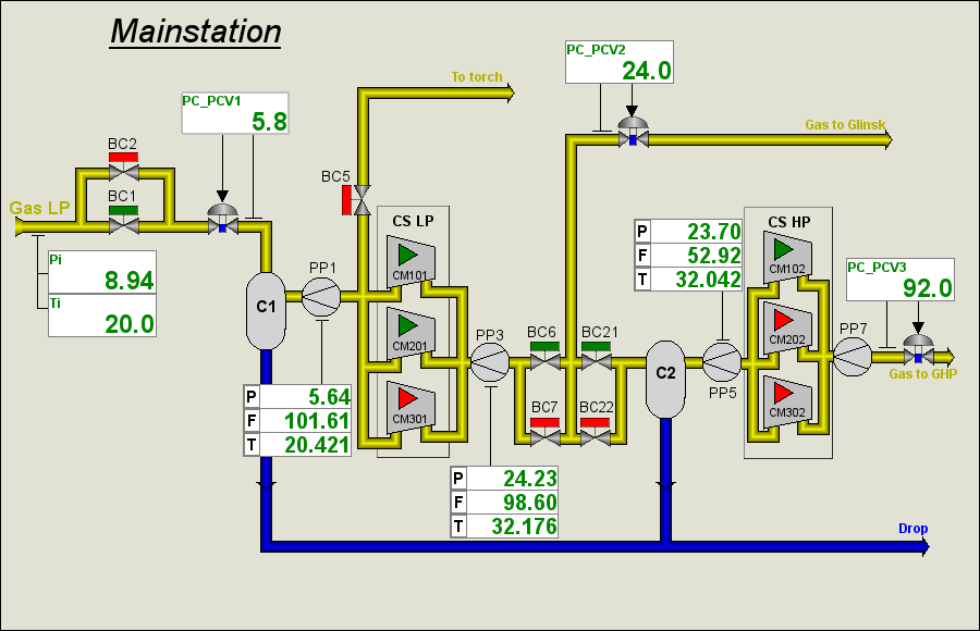
Before the creation of the GLKS simulator the schematic diagram of its technological process was formed, based on the schematic diagram of the real technological process. The scheme is shown in Figure 1.
2.2 Simulating-modeling
To construct the simulator of the technological process, basing on the available devices models, the original principal diagram and the block calculator (BlockCalc) of OpenSCADA were directly used. The devices models of the technological scheme were appended to the block scheme in accordance with the principal one. Part of the blocks were been added for the auxiliary equipment, as well as for the flow nodes. Numbers of the node blocks on the principal diagram are indicated by numbers near the flow nodes.
The model is made as eight block schemes of the block calculator. Content and properties of the block schemes are shown in Table 1.
Table 1. Block-scheme of the simulator
| Identifier | Name | Target | Execution period, seconds |
|---|---|---|---|
| gen | Mainstation | Contains the model of the general part of the compressor station, that is all that is shown on the principle scheme besides the gray blocks of individual compressors. | 0.01 |
| gen_cntr | Mainstation (controller) | Contains the model of the control system of the general part. | 1 |
| CM101 | Model of CM101 | Contains the model of the first compressor CM101 of low pressure. | 0.01 |
| CM102 | Model of CM102 | Contains the model of the first compressor CM102 of high pressure. | 0.01 |
| CM201 | Model of CM201 | Contains the model of the second compressor CM201 of low pressure. | 0.01 |
| CM202 | Model of CM202 | Contains the model of the second compressor CM202 of high pressure. | 0.01 |
| CM301 | Model of CM301 | Contains the model of the third compressor CM301 of low pressure. | 0.01 |
| CM302 | Model of CM302 | Contains the model of the third compressor CM302 of high pressure. | 0.01 |
Table 2 shows the list of used device models, in accordance with the principle diagram.
Table 2. Models of the used technological devices
| Model of the technological device | Devices (blocks of the simulator) |
|---|---|
| Ball crane (ballCrane) | gen.G_BC1, gen.G_BC2, gen.G_BC5, gen.G_BC6, gen.G_BC7, gen.G_BC21, G_BC22, CM*01.G_BC101, CM*01.G_BC102, CM*01.G_BC104, CM*01.G_BC105, CM*01.G_BC106, CM*02.G_BC111, CM*02.G_BC112, CM*02.G_BC114, CM*02.G_BC115, CM*02.G_BC116 |
| Gas compressor (compressor) | CM*01.CM101_1, CM*01.CM101_2, CM*02.CM102_1, CM*02.CM102_2 |
| Air cooler (cooler) | CM*01.AT101_1, CM*01.AT101_2, CM*02.AT102_1, CM*02.AT102_2 |
| Diaphragm (diafragma) | gen.PP1, gen.PP3, gen.PP5, gen.PP7, CM*01.PP101, CM*01.PP102, CM*02.PP103, CM*02.PP104 |
| Valve (klap) | gen.BC1, gen.BC5, gen.BC6, gen.BC21, CM*01.KPP101, CM*01.DR100, CM*01.BC101, CM*01.BC104, CM*01.BC106, CM*02.KPP102, CM*02.DR101, CM*02.BC111, CM*02.BC113, CM*02.BC114, CM*02.BC116 |
| Lag (lag) | gen.P_PCV2 |
| Network, load (net) | gen.netHPG, gen.netGlinsk, gen.netTorch, CM*02.net102 |
| Pipe 1->1 (pipe1_1) | gen.pipeGlinsk |
| Pipe 1->2 (pipe1_2) | gen.node1, gen.node20 |
| Pipe 1->3 (pipe1_3) | gen.node1_1, gen.node21, CM*01.node4_1 |
| Pipe 1->4 (pipe1_4) | CM*02.node6_1 |
| Pipe 3->1 (pipe3_1) | gen.node22, gen.node19, CM*01.node3_1, CM*02.node5_1 |
| Noise, 2 harmonic + rand (noise) | gen.noisePP3 |
| Separator (separator) | gen.C1, gen.C2, CM*01.C101_1, CM*01.C101_2, CM*01.C101_3, CM*02.С102_1, CM*02.С102_2, CM*02.С102_3 |
| Source, pressure (src_press) | gen.SrcGas |
Through the using of the library of the models of tech. devices and concepts for building the dynamic models it has been obtained the dynamic model, from which you can get the parameters at any point of the principle scheme as for the study and for testing of the control algorithms.
For information about the technological process the parameters were created (Table 3), which provide data from selected nodes of the simulator.
Table 3. Parameters of the technological process
| Cipher | Description | Properties | Source |
|---|---|---|---|
| Mainstation (BlockCalc.gen) | |||
| F2, F_PP1 | Gas flow through the diaphragm PP1 | PP1.Fi | |
| F3 | Gas flow through the pipe to Glinsk | pipeGlinsk.Fi | |
| F4, F_PP5, F5_6 | Gas flow through the diaphragm PP5 | PP5.Fi | |
| F7_8 | Gas flow through the diaphragm PP7 | PP7.Fi | |
| F_PP3 | Gas flow through the diaphragm PP3 | PP3.Fo | |
| BC1 | Control block of the ball crane BC1 | G_BC1.com, G_BC1.st_open, G_BC1.st_close | |
| BC2 | Control block of the ball crane BC2 | G_BC2.com, G_BC2.st_open, G_BC2.st_close | |
| BC5 | Control block of the ball crane BC5 | G_BC5.com, G_BC5.st_open, G_BC5.st_close | |
| BC6 | Control block of the ball crane BC6 | G_BC6.com, G_BC6.st_open, G_BC6.st_close | |
| BC7 | Control block of the ball crane BC7 | G_BC7.com, G_BC7.st_open, G_BC7.st_close | |
| BC21 | Control block of the ball crane BC21 | G_BC21.com, G_BC21.st_open, G_BC21.st_close | |
| BC22 | Control block of the ball crane BC22 | G_BC22.com, G_BC22.st_open, G_BC22.st_close | |
| L1 | Liquid level in the separator C2 | C2.Lж | |
| Ti | Gas temperature at the input of the CS | BC1.Ti | |
| T_PP1 | Gas temperature at the diaphragm PP1 | PCV1.To | |
| T_PP3 | Gas temperature at the diaphragm PP3 | node19.To | |
| T_PP5 | Gas temperature at the diaphragm PP5 | BC21.To | |
| Pi | Gas pressure at the input of the CS | BC1.Pi | |
| P_PP1 | Gas pressure at the diaphragm PP1 | PP1.Po | |
| P_PP3, PC0601 | Gas pressure at the diaphragm PP3 | PP3.Po | |
| P_PP5, P4, PT0404 | Gas pressure at the diaphragm PP5 | PP5.Po | |
| PT0804, P3 | Gas pressure in the pipe to Glinsk | pipeGlinsk.Pi | |
| PT1606, PT0503 | Gas pressure in the separator С1 | C1.Po | |
| PT0406 | Gas pressure at the diaphragm PP7 | PP7.Po | |
| PT0605 | Gas pressure before the control valve PCV1 | PCV1.Pi | |
| Mainstation (LogicLev.gen) | |||
| F3 | Gas flow through the pipe to Glinsk | Template: base.anUnif t/h, (0;100), a(10;90), w(35;80) |
BlockCalc.gen.F3.var |
| F4, F_PP5 | Gas flow through the diaphragm PP5 | Template: base.anUnif t/h, (0;100), a(10;90), w(35;80) |
BlockCalc.gen.F4.var, BlockCalc.gen.F_PP5.var |
| F_PP1 | Gas flow through the diaphragm PP1 | Template: base.anUnif t/h, (0;150) |
BlockCalc.gen.F_PP1.var |
| F_PP3 | Gas flow through the diaphragm PP3 | Template: base.anUnif t/h, (0;150) |
BlockCalc.gen.F_PP3.var |
| Ti | Gas temperature at the input of the CS | Template: base.anUnif deg. С, (-50;50), a(-20;40), w(-10;30) |
BlockCalc.gen.Ti.var |
| T_PP1 | Gas temperature at the diaphragm PP1 | Template: base.anUnif deg. С, (0;50) |
BlockCalc.gen.T_PP1.var |
| T_PP3 | Gas temperature at the diaphragm PP3 | Template: base.anUnif deg. С, (0;50) |
BlockCalc.gen.T_PP3.var |
| T_PP5 | Gas temperature at the diaphragm PP5 | Template: base.anUnif deg. С, (0;50) |
BlockCalc.gen.T_PP5.var |
| Pi | Gas pressure at the input of the CS | Template: base.anUnif kgf/cm2, (0;20), a(4;15), w(5;10) |
BlockCalc.gen.Pi.var |
| P3 | Gas pressure in the pipe to Glinsk | Template: base.anUnif kgf/cm2, (0;100), a(10;90), w(20;80) |
BlockCalc.gen.P3.var |
| P_PP1 | Gas pressure at the diaphragm PP1 | Template: base.anUnif kgf/cm2, (0;10) |
BlockCalc.gen.P_PP1.var |
| P_PP3 | Gas pressure at the diaphragm PP3 | Template: base.anUnif kgf/cm2, (0;50) |
BlockCalc.gen.P_PP3.var |
| P_PP5, P4 | Gas pressure at the diaphragm PP5 | Template: base.anUnif kgf/cm2, (0;50) |
BlockCalc.gen.P_PP5.var, BlockCalc.gen.P4.var |
| PT0503 | Gas pressure in the separator С1 | Template: base.anUnif kgf/cm2, (0;10), a(2;8), w(3;7) |
BlockCalc.gen.PT0503.var |
| BC6close | Alarm of closing the crane BC6 | Template: base.digAlarm | BlockCalc.gen.BC6.st_open |
| gN1 | Account node of the diaphragm PP1 | Template: base.gasPoint | |
| BC7 | Control block of the ball crane BC7 | Template: base.digitBlock t=5s |
BlockCalc.gen.BC7.com, BlockCalc.gen.BC7.st_open, BlockCalc.gen.BC7.st_close |
| Mainstation controller (BlockCalc.gen_cntr) | |||
| PC_PCV1 | Regulator of the input pressure of the CS | at, (0;10) | PC_PCV1.* |
| PC_PCV2 | Regulator of the pressure between of the low and high pressure compressors | at, (0;50) | PC_PCV2.* |
| PC_PCV3 | Regulator of the pressure at the output of the CS | at, (0;120) | PC_PCV3.* |
| SurgeCM101 | Regulator of the surge protection of the compressor CM101 | at, (0;2) | SurgeCM101.sp:sp |
| SurgeCM102 | Regulator of the surge protection of the compressor CM102 | at, (0;2) | SurgeCM102.sp:sp |
| SurgeCM201 | Regulator of the surge protection of the compressor CM201 | at, (0;2) | SurgeCM201.sp:sp |
| SurgeCM202 | Regulator of the surge protection of the compressor CM202 | at, (0;2) | SurgeCM202.sp:sp |
| SurgeCM301 | Regulator of the surge protection of the compressor CM301 | at, (0;2) | SurgeCM301.sp:sp |
| SurgeCM302 | Regulator of the surge protection of the compressor CM302 | at, (0;2) | SurgeCM302.sp:sp |
| Model of CM*01 (BlockCalc.CM*01) | |||
| KPP101 | Anti-surge control valve of the compressor | %, (0;100), 0 digits | KPP101.l_kl1 |
| FN101 | Flow at the output of the compressor | BC104.Fi | |
| F101 | Flow on the diaphragm PP101 | t/h, (0;100), 1 digit | PP101.Fi |
| F102 | Flow on the diaphragm PP102 | t/h, (0;100), 1 digit | PP102.Fi |
| TE1202_1 | Temperature after the first stage of the compressor | K, (273;373), 0 digit | CM101_1.To |
| TE1205_1 | Temperature after the second stage of the compressor | K, (273;433), 0 digit | CM101_2.To |
| TE1313_1 | Temperature at the input of the first stage of the compressor | K, (273;373), 0 digit | node5_1.To |
| TE1314_1 | Temperature after the fridge of the first stage of the compressor | K, (273;373), 0 digit | AT101_1.To |
| TE1206_1 | Temperature after the fridge of the second stage of the compressor | K, (273;373), 0 digit | AT101_2.To |
| AT101_1 | Control block of the fridge after the first stage of the compressor | AT101_1.Ti, AT101_1.To, AT101_1.Wc | |
| AT101_2 | Control block of the fridge after the second stage of the compressor | AT101_2.Ti, AT101_2.To, AT101_2.Wc | |
| BC101 | Control block of the ball crane BC101 | G_BC101.com, G_BC101.st_open, G_BC101.st_close | |
| BC102 | Control block of the ball crane BC102 | G_BC102.com, G_BC102.st_open, G_BC102.st_close | |
| BC104 | Control block of the ball crane BC104 | G_BC104.com, G_BC104.st_open, G_BC104.st_close | |
| BC105 | Control block of the ball crane BC105 | G_BC105.com, G_BC105.st_open, G_BC105.st_close | |
| BC106 | Control block of the ball crane BC106 | G_BC106.com, G_BC106.st_open, G_BC106.st_close | |
| PT0202_1 | Pressure after the first stage of the compressor | at, (0;20), 1 digit | CM101_1.Po |
| PT0204_1 | Pressure after the second stage of the compressor | at, (0;50), 1 digit | CM101_2.Po |
| PT1006_1 | Pressure on the diaphragm PP102 | at, (0;20), 1 digit | PP102.Pi |
| P101 | Pressure on the diaphragm PP101 | at, (0;10), 1 digit | PP101.Pi |
| ST8612_1 | Rotation speed of the compressor | 1000x rpm, (0;10), 2 digits | CM101_1.N |
| Model of CM*01 (BlockCalc.CM*02) | |||
| KPP102 | Anti-surge control valve of the compressor | %, (0;100), 0 digits | KPP102.l_kl1 |
| TE1202_4 | Temperature after the first stage of the compressor | K, (273;373), 0 digit | CM102_1.To |
| TE1205_4 | Temperature after the second stage of the compressor | K, (273;433), 0 digit | CM102_2.To |
| TE1313_4 | Temperature at the input of the first stage of the compressor | K, (273;373), 0 digit | node5_1.To |
| TE1314_4 | Temperature after the fridge of the first stage of the compressor | K, (273;373), 0 digit | AT102_1.To |
| TE1206_4 | Temperature after the fridge of the second stage of the compressor | K, (273;373), 0 digit | AT102_2.To |
| F103 | Flow on the diaphragm PP103 | t/h, (0;100), 1 digit | PP103.Fi |
| F104 | Flow on the diaphragm PP104 | t/h, (0;100), 1 digit | PP104.Fi |
| PT0202_4 | Pressure after the first stage of the compressor | at, (0;75), 1 знак | CM102_1.Po |
| PT0204_4 | Pressure after the second stage of the compressor | at, (0;150), 1 знак | CM102_2.Po |
| PT1006_4 | Pressure on the diaphragm PP104 | at, (0;75), 1 digit | PP104.Pi |
| P103 | Pressure on the diaphragm PP103 | at, (0;50), 1 digit | PP103.Pi |
| BC111 | Control block of the ball crane BC111 | G_BC111.com, G_BC111.st_open, G_BC111.st_close | |
| BC112 | Control block of the ball crane BC112 | G_BC112.com, G_BC112.st_open, G_BC112.st_close | |
| BC114 | Control block of the ball crane BC114 | G_BC114.com, G_BC114.st_open, G_BC114.st_close | |
| BC115 | Control block of the ball crane BC115 | G_BC115.com, G_BC115.st_open, G_BC115.st_close | |
| BC116 | Control block of the ball crane BC116 | G_BC116.com, G_BC116.st_open, G_BC116.st_close | |
| ST8612_4 | Rotation speed of the compressor | 1000x rpm, (0;15), 2 digits | CM102_1.N |
2.3 Regulation
The dynamic model-simulator itself may be unstable without control, although in this case there are no unbalanced integrated circuits. For this reason, as well as to create a self-sufficient simulator capable of operating autonomously and without the PLC as a regulator, an object was created for the regulators controller of the simulator where three common PID regulators PC_PCV1, PC_PCV2 and PC_PCV3 are implemented for controlling the pressure at the CS input, between the low and high pressure compressors, and also at the output of the CS. There are also six anti-surge protectors SurgeCM*0*, one for compressor.
3 User interface
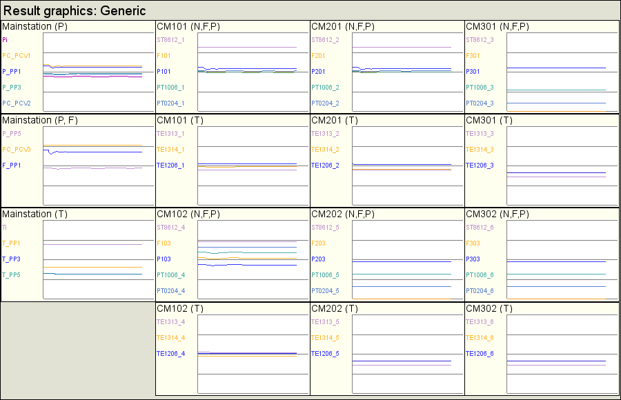
User interface of the simulator contains seven signaling objects (Fig.2). Six of them contain frames of the compressors CM101, CM201, CM301, CM102, CM202 and CM302. The seventh is common for the entire compressor station and contains mainstation frames. Mainstation signaling group includes two mnemonic scheme, two groups of graphs, a group of contours, an overview frame and five documents. One general review group of the result graphics is also provided.
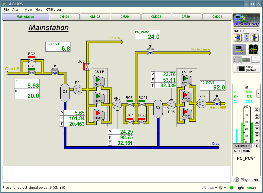
The mnemonic schemes of the signaling object "Mainstation" are resented in Figure 3 and 4.
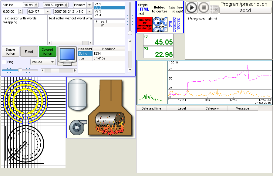
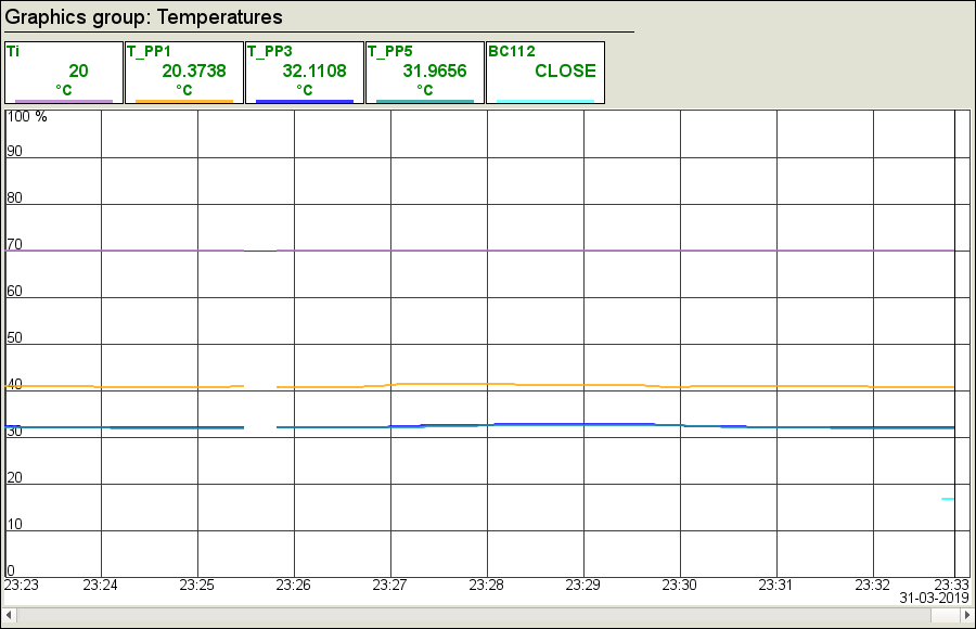
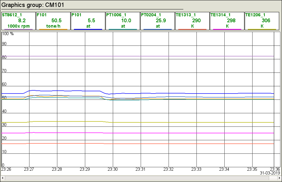
The graphics groups "Generic" and "Temperatures" are presented at Figure 5 and 6, respectively.
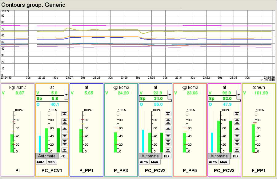
The contours group "Generic" (Fig. 7) contains the contours of all the regulators and a set of important parameters.
The group "Generic" (Fig. 8) of the overview frames contains the frames of the main parameters.
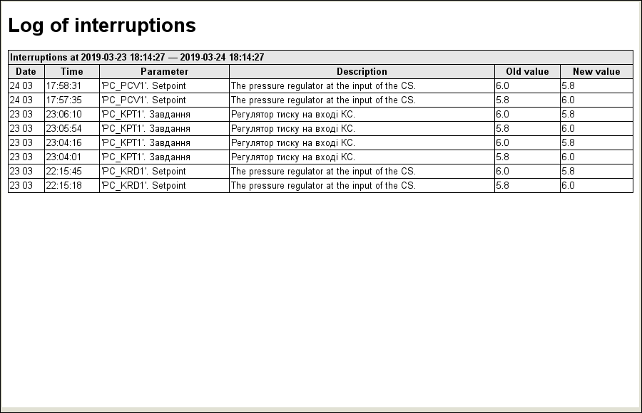
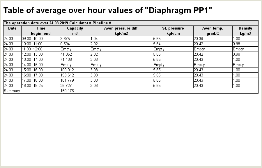
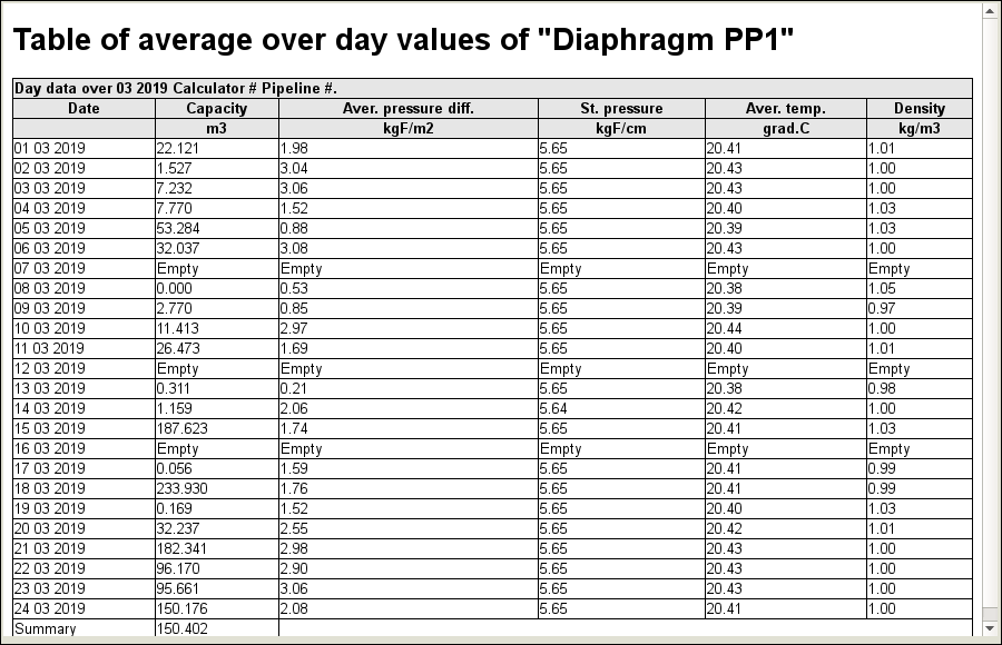
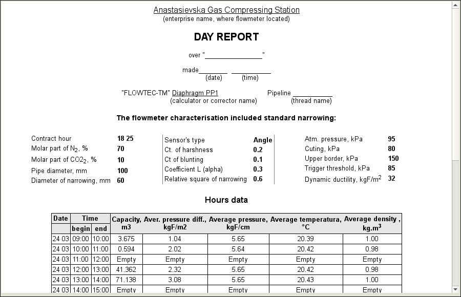
The documents "Table of accumulation instantaneous values", "Log of interruptions", "Table of average over hour values", "Table of average over day values" and "Day Report" are presented in Figure 9, 10, 11, 12 and 13, respectively.
Signaling objects of the compressors of low pressure contain a mnemonic scheme (Fig.14) and a graphics group (Fig.15).
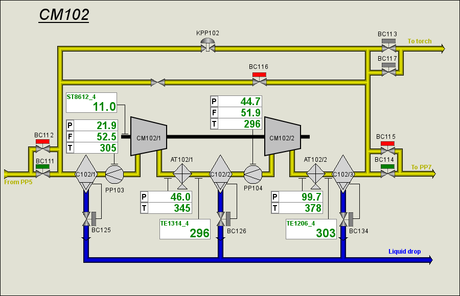
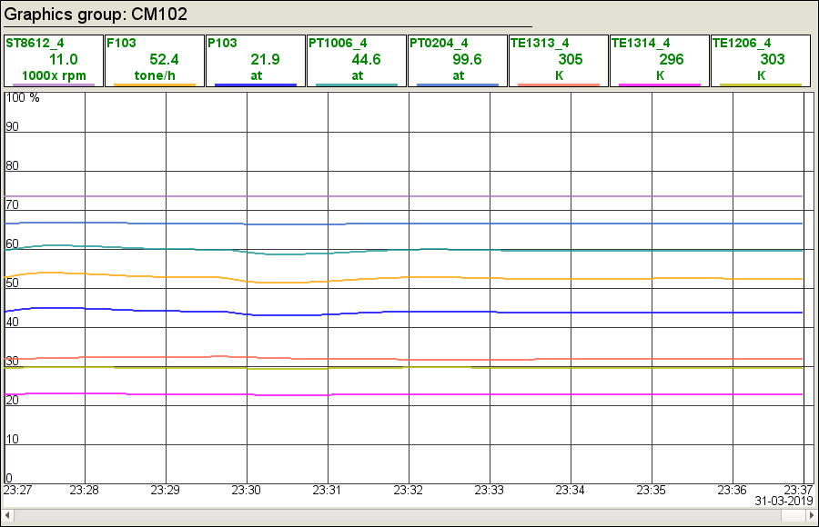
Signaling objects of the high pressure compressors contain a mnemonic scheme (Fig.16) and a graphics group (Fig.17).
To display the dynamics of the entire compressor station a group of the result graphics are provided (Fig.18)
4 Results
The result of the development is the complete dynamic model of technological process of the compressor station. This model is available in three languages and is included in the distributions of OpenSCADA as the generic demonstration of features and capabilities, and on its basis the document "Quick start" was built.
The model envisages the ability to control the TP on behalf of the operator, including operations:
- control the pressure regulators:
- changing the regulator mode: "Automatic" or "Manual";
- setting the desirable setpoint value or manual output of the executive mechanism;
- configuration the PID-regulator parameters.
- control of latches and ball valves through the control panel and the context menu by closing or opening;
- manual entry of the values of the parameters of the rotations (ST8612) and the position of the anti-surge valves (KPPx0x).
The model was successfully applied for debugging algorithms of the surge protection of the compressors of the Anastasievskaja GLKS.
Resource intensity of the simulator in whole, to the CPU Athlon 64 3000+ (2000MHz) is 22%, to the CPU 800 MHz is 70%.

