| Название | Версия | Лицензия | Источник | Языки | Автор | Описание |
|---|---|---|---|---|---|---|
| Библиотека низкоуровневых сенсоров и чипов | 1.6 | GPLv2 | OscadaLibs.db (SQL, GZip) > DAQ.tmplb_LowDevLib | en, uk, ru | Roman Savochenko Arcadiy Kisel (2017) |
Library of templates to provide access to device's data of the low-level buses.
|
Библиотека устройств пользовательских протоколов создана для предоставления доступа к данным устройств низкоуровневых шин, с протоколом достаточно простым для реализации в модуле пользовательского протокола или непосредственно на внутреннем языке подобном на Java.
Названия элементов и их параметров доступны на языках: Английский, Украинский и mRussian. Их исходный код написан в языко(человеческий)-независимом режиме с вызовом функции перевода tr() и перевод этих сообщений также доступен Английским, Украинским и mRussian.
Для подключения библиотеки к проекту станции OpenSCADA Вы можете получить файл БД как:
- такой что поставляется с готовым и соответствующим пакетом дистрибутива Linux вроде "openscada-libdb-main", "openscada-LibDB.Main";
- наиболее актуальный и непосредственно полученный из репозитория subversion, преобразованный в файл БД SQLite путём:
wget http://oscada.org/svn/trunk/OpenSCADA/data/LibsDB/OscadaLibs.sql
sqlite3 -init OscadaLibs.sql OscadaLibs.db .exit
- загрузка прикреплённого тут.
Этот загруженный файл вы далее можете разместить в каталоге проекта станции и создать объект базы данных модуля БД "SQLite", зарегистрировав файл базы данных в конфигурации.
Contents
- 1 BT: RDTech UM24C, UM25C and UM34C (RDTech)
- 2 BT: ATORCH UC96, UD24 (UC96)
- 3 BT: ATORCH S1BP (S1BP)
- 4 1-Wire (1W)
- 5 I2C: PCF8591 (PCF8591)
- 6 I2C: PCF8574 (PCF8574)
- 7 I2C: ADS101x, ADS111x (ADS111x)
- 8 I2C: MCP4725 (MCP4725)
- 9 I2C: BMP180 (BMP180)
- 10 I2C: BME280 (BME280)
- 11 I2C: SHT3x (SHT3x)
- 12 I2C: DS1307,DS3231 (DS3231)
- 13 I2C: AT24C{32|64} (AT24CXX)
- 14 GPIO: DHT11,22 (DHT)
- 15 GPIO: MAX6675 (MAX6675)
- 16 GPIO|I2C: 1602A(HD44780) (1602A)
Для DAQ-шаблонов, в целом, вам нужно создать представительский объект устройства в модуле Логического Уровня и выбрать соответствующий шаблон из библиотеки шаблонов. Далее, для корректной конфигурации, придерживайтесь специфики шаблона в персональном описании. Концепцию доступа к данным через пользовательский протокол можно изобразить как на рисунке 1.
Как можно видеть с рисунка 1, взаимодействие с устройством происходит через некоторый транспорт на котором они физически базируются. Запрос к транспорту Вы можете отправить:
- Непосредственно с помощью функции системного API OpenSCADA объекта транспорта string messIO( string mess, real timeOut = 0 );, если протоколоспецифическая часть очень проста и данные Вам нужно лишь извлечь.
- Завёрнутый запрос данных req, функцией int messIO( XMLNodeObj req, string prt ); и для протокола prt, если протокольная часть достаточно сложная и уже представлена в OpenSCADA.
- Завёрнутый запрос данных специфический к пользователю с помощью функции int messIO( XMLNodeObj req, "UserProtocol" ); и реализации пользовательского протокола, если протокольная часть достаточно сложная и ещё отсутствует в OpenSCADA. Пользователь реализует тут саму протоколоспецифическую часть в модуле UserProtocol и часть специфическую к данным в шаблоне для модуля Логического Уровня или непосредственно в процедуре контролера на внутреннем языке программирования модуля JavaLikeCalc.
-
 Этот последний метод развит к возможности формирования протокольной части кода непосредственно в том-же коде шаблона, как отдельная встроенная функция через вызовом функции запроса первого метода, если нет необходимости повторного использования, или даже если такая необходимость есть и тут имеет смысл создание комплексного шаблона, который сможет объединять роль и выходного протокола, через его подключение также к модулю пользовательского протокола. И оно будет полностью храниться в одной библиотеке шаблонов.
-
![]() Прямая работа с выходным транспортом функции string messIO( string mess, real timeOut = 0 ); не предусматривает блокирования транспорта поза вызовом этой функции, а соответственно, для сложных протоколов с посылками ответа более чем в одном пакете, что предусматривает процесс "дожидания", не можно использовать общий транспорт, по которому возможна отправка пакетов различных протоколов или даже один, но в различных задачах (объектах контроллеров). Соответственно, если есть необходимость использования совместного транспорта, то размещайте параметры опроса по протоколу в одном объекте контроллера (задаче) или используйте модуль пользовательского протокола, к которому это замечание не имеет отношения, поскольку он осуществляет такое блокирование на время вызова процедуры обработки, как и остальные модульные протоколы OpenSCADA.
Для размещения реализации протокола тут вы должны выполнить и придерживаться приведенных требований:
Прямая работа с выходным транспортом функции string messIO( string mess, real timeOut = 0 ); не предусматривает блокирования транспорта поза вызовом этой функции, а соответственно, для сложных протоколов с посылками ответа более чем в одном пакете, что предусматривает процесс "дожидания", не можно использовать общий транспорт, по которому возможна отправка пакетов различных протоколов или даже один, но в различных задачах (объектах контроллеров). Соответственно, если есть необходимость использования совместного транспорта, то размещайте параметры опроса по протоколу в одном объекте контроллера (задаче) или используйте модуль пользовательского протокола, к которому это замечание не имеет отношения, поскольку он осуществляет такое блокирование на время вызова процедуры обработки, как и остальные модульные протоколы OpenSCADA.
Для размещения реализации протокола тут вы должны выполнить и придерживаться приведенных требований:
- быть владельцем прав или автором кода и распространять его под любой свободной лицензией, предпочтение предоставляется GPL;
- приготовить и сохранить в отдельном файле БД SQLite, или как текстовый файл, на предмет: описания параметров (ВВ), кода процедуры написанного и отформатированного согласно какой нидудь системы;
- написать краткое описание и инструкцию подключения устройства по протоколу в способ похожий на другие тут;
- написать прямой запрос в тему форума "Разработка OpenSCADA" на предмет размещения протокола тут, включая доказательства его работоспособности от любого разработчика OpenSCADA или краткое демонстрационное видео.
1 BT: RDTech UM24C, UM25C and UM34C (RDTech) |
1.1 | GPLv2 | * | en,uk | Roman Savochenko |
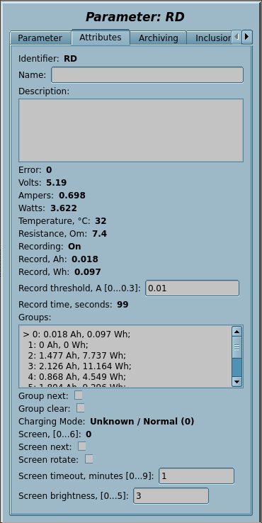
RDTech UM24C/UM25C/UM34C BlueTooth interface template. ![]() Tested only on UM24C now.
Tested only on UM24C now.
The RDTech (RuiDeng) UM24C, UM25C and UM34C are low-cost USB pass-through power measurement devices, and support a decent number of collection features, as well as full control via Bluetooth. This template implements most exposed commands and data collection available by the device's Bluetooth interface.
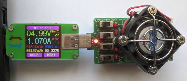
This template in first time uses the new output transports connection function SYS.Transport.outAt() and the Bluetooth interface for the data acquisition.
- Total complexity: 0.3 HD[!]
- Thanks: for Ryan Finnie at the protocol initial processing in RDUMTOOL
Template IOs
| Identifier | Parameter | Type | Mode | Attribute | Configuration | Value |
|---|---|---|---|---|---|---|
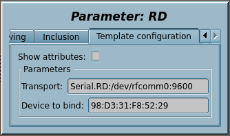
| transport | Transport | String | Input | Not attribute | Constant | Serial.RD:/dev/rfcomm0:9600||1000:40-20 |
| dev | Device to bind
Like to "98:D3:31:F8:52:29" for binding by "rfcomm bind {N} 98:D3:31:F8:52:29". |
String | Input | Not attribute | Constant | |
| V | Volts | Real | Input | Read only | Variable | |
| A | Amperes | Real | Input | Read only | Variable | |
| W | Watts | Real | Input | Read only | Variable | |
| T | Temperature, °С | Integer | Input | Read only | Variable | |
| R | Resistance, Om | Real | Input | Read only | Variable | |
| rec | Recording | Boolean | Input | Read only | Variable | |
| recAh | Record, Ah | Real | Input | Read only | Variable | |
| recWh | Record, Wh | Real | Input | Read only | Variable | |
| recThr | Record threshold, A [0...0.3] | Real | Input | Full access | Variable | |
| recTm | Record time, seconds | Real | Input | Read only | Variable | |
| grps | Groups | Text | Input | Read only | Variable | |
| grpNext | Group next | Boolean | Input | Full access | Variable | |
| grpClear | Group clear | Boolean | Input | Full access | Variable | |
| chMode | Charging Mode | String | Input | Read only | Variable | |
| scr | Screen, [0...6] | Integer | Input | Read only | Variable | |
| scrNext | Screen next | Boolean | Input | Full access | Variable | |
| scrRot | Screen rotate | Boolean | Input | Full access | Variable | |
| scrTm | Screen timeout, minutes [0...9] | Integer | Input | Full access | Variable | |
| scrBright | Screen brightness, [0...5] | Integer | Input | Full access | Variable | |
| this | Object | Object | Input | Not attribute | Variable | |
| f_err | Function error | String | Input | Not attribute | Variable | 0 |
| f_stop | Function stop flag | Boolean | Input | Not attribute | Variable | 0 |
| f_start | Function start flag | Boolean | Input | Not attribute | Variable | 0 |
| f_frq | Frequency of calculation of the function, Hz | Real | Input | Not attribute | Variable | 1000 |
Configuring and using
- 1. Connection the BlueTooth device:
bluetoothctl
#[bluetooth]# scan on
#  Discovery started
#  [NEW] Device 98:D3:31:F8:52:29 UM24C
#  [CHG] Device 98:D3:31:F8:52:29 RSSI: -60
#[bluetooth]# scan off
#[bluetooth]# pair 98:D3:31:F8:52:29
#  Attempting to pair with 98:D3:31:F8:52:29
#  [CHG] Device 98:D3:31:F8:52:29 Connected: yes
#  Request PIN code
#  [UM241m[agent] Enter PIN code: 1234
#  Pairing successful
#[bluetooth]# trust 98:D3:31:F8:52:29
#  [CHG] Device 98:D3:31:F8:52:29 Trusted: yes
#  Changing 98:D3:31:F8:52:29 trust succeeded
#[bluetooth]# exit

rfcomm bind 0 98:D3:31:F8:52:29   # 0 here for binding to /dev/rfcomm0
- 2. Create and start a logical controller object or use any presented one with the needed scheduling properties.
- 3. Create a logical parameter object and select this template for it, one for each the devices. Enable the parameter.
- 4. Into the tab "Template configuration" of the logical parameter object you need to set:
- Transport — to the address of the automatically created transport with its parameters after ":", according to the function SYS.Transport.outAt() address format, where the device address corresponds to the command rfcomm bind 0 in item 1.
- Device to bind — here you may set the Bluetooth address of the device as "98:D3:31:F8:52:29" to call the rfcomm bind {N} command when starting the template, where N is respectively taken from the address of the previous item.
- 5. RESULT: The logical parameter object will perform gather data of and trace to modify of the writable properties.
2 BT: ATORCH UC96, UD24 (UC96) |
1.2 | GPLv2 | * | en,uk | Roman Savochenko |
ATORCH UC96, UD24 BlueTooth interface template.
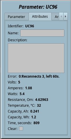
The ATORCH UC96, UD24 are low-cost USB pass-through power measurement device with many interfaces and supporting a decent number of collection features, as well as control via Bluetooth. This template implements only the clearing data command and data collection by the device's Bluetooth interface.
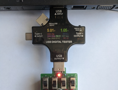
The device sends data packages not at a request and just after establishing the connection, that is broadcasting with one second period. ![]() The device may not to send the data packages at enable not in the first screen, so you need to switch the first screen for the data appearance. The data can be missed also after suspending the PC, so this template in the first time implements the data missing detection and reconnection.
The device may not to send the data packages at enable not in the first screen, so you need to switch the first screen for the data appearance. The data can be missed also after suspending the PC, so this template in the first time implements the data missing detection and reconnection.
- Total complexity: 0.3 HD[!]
Template IOs
| Identifier | Parameter | Type | Mode | Attribute | Configuration | Value |
|---|---|---|---|---|---|---|
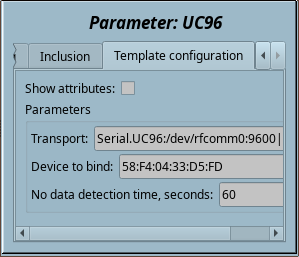
| transport | Transport | String | Input | Not attribute | Constant | Serial.UC96:/dev/rfcomm0:9600||1000:40-20 |
| dev | Device to bind
Like to "58:F4:04:33:D5:FD" for binding by "rfcomm bind {N} 58:F4:04:33:D5:FD". |
String | Input | Not attribute | Constant | |
| noDataTm | No data detection time, seconds | Integer | Input | Not attribute | Constant | 60 |
| V | Volts | Real | Input | Read only | Variable | |
| Vup | Volts maximum | Real | Input | Read only | Variable | |
| Vdwn | Volts minimum | Real | Input | Read only | Variable | |
| A | Amperes | Real | Input | Read only | Variable | |
| W | Watts | Real | Input | Read only | Variable | |
| R | Resistance, Om | Real | Input | Read only | Variable | |
| T | Temperature, °С | Integer | Input | Read only | Variable | |
| Ah | Capacity, Ah | Real | Input | Read only | Variable | |
| Wh | Capacity, Wh | Real | Input | Read only | Variable | |
| Tm | Time, seconds | Integer | Input | Read only | Variable | |
| Dplus | Data+, V | Real | Input | Read only | Variable | |
| Dminus | Data-, V | Real | Input | Read only | Variable | |
| clear | Clear | Boolean | Input | Full access | Variable | |
| this | Object | Object | Input | Not attribute | Variable | |
| f_err | Function error | String | Input | Not attribute | Variable | 0 |
| f_stop | Function stop flag | Boolean | Input | Not attribute | Variable | 0 |
| f_start | Function start flag | Boolean | Input | Not attribute | Variable | 0 |
| f_frq | Frequency of calculation of the function, Hz | Real | Input | Not attribute | Variable | 1000 |
Configuring and using
- 1. Connection the BlueTooth device: performed in the standard way of pairing and trusting without PIN and to UC96_SPP
- 2. Create and start a logical controller object or use any presented one with the needed scheduling properties.
- 3. Create a logical parameter object and select this template for it, one for each the devices. Enable the parameter.
- 4. Into the tab "Template configuration" of the logical parameter object you need to set:
- Transport — to the address of the automatically created transport with its parameters after ":", according to the function SYS.Transport.outAt() address format, where the device address corresponds to the command rfcomm bind 0.
- Device to bind — here you may set the Bluetooth address of the device as "58:F4:04:33:D5:FD" to call the rfcomm bind {N} command when starting the template, where N is respectively taken from the address of the previous item.
 The rfcomm command is normally not available to be called by a non-privileged user, and if you want to call it by such a user, you must set a corresponding sign for it as chmod u+s /usr/bin/rfcomm from the super user.
- No data detection time — here you may set the time of detection of the data missing.
- 5. RESULT: The logical parameter object will perform gather data of and trace to modify of the writable properties.
3 BT: ATORCH S1BP (S1BP) |
1.0 | GPLv2 | * | en,uk | Roman Savochenko |
ATORCH S1BP BlueTooth interface template.
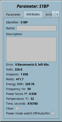
The ATORCH S1BP is low-cost AC energy measurement device with supporting a decent number of collection features, as well as control via Bluetooth. This template implements the command of the data clearing and switching the power mode, also as collection the data by the device's Bluetooth interface.

The device sends data packages not at a request and just after establishing the connection, that is broadcasting with one second period.
- Total complexity: 0.1 HD[!]
Template IOs
| Identifier | Parameter | Type | Mode | Attribute | Configuration | Value |
|---|---|---|---|---|---|---|
| transport | Transport | String | Input | Not attribute | Constant | Serial.S1BP:/dev/rfcomm2:9600||1000:40-20 |
| dev | Device to bind
Like to "40:2B:6D:EF:48:A7" for binding by "rfcomm bind {N} 40:2B:6D:EF:48:A7". |
String | Input | Not attribute | Constant | |
| noDataTm | No data detection time, seconds | Integer | Input | Not attribute | Constant | 60 |
| V | Volts | Real | Input | Read only | Variable | |
| A | Amperes | Real | Input | Read only | Variable | |
| W | Watts | Real | Input | Read only | Variable | |
| KWh | Energy, KWh | Real | Input | Read only | Variable | |
| Hz | Frequency, Hz | Real | Input | Read only | Variable | |
| Pf | Power factor, Pf | Real | Input | Read only | Variable | |
| T | Temperature, °С | Integer | Input | Read only | Variable | |
| Tm | Time, seconds | Integer | Input | Read only | Variable | |
| clear | Clear | Boolean | Input | Full access | Variable | |
| power | Power mode switch Off/Auto/On | Boolean | Input | Full access | Variable | |
| this | Object | Object | Input | Not attribute | Variable | |
| f_stop | Function stop flag | Boolean | Input | Not attribute | Variable | 0 |
| f_start | Function start flag | Boolean | Input | Not attribute | Variable | 0 |
| f_frq | Frequency of calculation of the function, Hz | Real | Input | Not attribute | Variable | 1000 |
| f_err | Function error | String | Input | Not attribute | Variable | 0 |
Configuring and using
- 1. Connection the BlueTooth device: performed in the standard way of pairing and trusting without PIN and to S1BP_SPP
- 2. Create and start a logical controller object or use any presented one with the needed scheduling properties.
- 3. Create a logical parameter object and select this template for it, one for each the devices. Enable the parameter.
- 4. Into the tab "Template configuration" of the logical parameter object you need to set:
- Transport — to the address of the automatically created transport with its parameters after ":", according to the function SYS.Transport.outAt() address format, where the device address corresponds to the command rfcomm bind 0.
- Device to bind — here you may set the Bluetooth address of the device as "58:F4:04:33:D5:FD" to call the rfcomm bind {N} command when starting the template, where N is respectively taken from the address of the previous item.
 The rfcomm command is normally not available to be called by a non-privileged user, and if you want to call it by such a user, you must set a corresponding sign for it as chmod u+s /usr/bin/rfcomm from the super user.
- No data detection time — here you may set the time of detection of the data missing.
- 5. RESULT: The logical parameter object will perform gather data of and trace to modify of the writable properties.
4 1-Wire (1W) |
2.1 | GPLv2 | * | en,uk | Roman Savochenko |
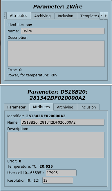
One Wire One Wire sensors bus implementing by 1Wire adaptors DS9097, DS9097U (DS2480B) on the bus RS232 and by the chip DS2482-100 on the bus I2C. Supported direct and parasite powering for the temperature sensors.
Supported 1Wire devices: DS1820, DS1820/DS18S20/DS1920 (not tested), DS1822 (not tested), DS2413, DS2408, DS2450, DS2438.

Template IOs
| Identifier | Parameter | Type | Mode | Attribute | Configuration | Value |
|---|---|---|---|---|---|---|
| transport | Transport | String | Input | Not attribute | Constant | 1Wire:/dev/ttyS0 |
| addr | Address of the I2C driver
[24...27] - for DS2482-100 |
Integer | Input | Not attribute | Constant | 24 |
| tmResc | Rescan period, seconds | Real | Input | Not attribute | Constant | 60 |
| onlyAddAtScan | Only add at scan | Boolean | Input | Not attribute | Constant | 0 |
| tryEVAL | Tries after which set value to EVAL | Integer | Input | Not attribute | Constant | 3 |
| adapterS | Type of the detected adaptor | String | Input | Read only | Variable | No detected |
| adapter | Code of the detected adaptor | Integer | Input | Not attribute | Variable | -1 |
| power | Power, for temperature | Boolean | Input | Read only | Variable | |
| isData | In data mode | Boolean | Input | Not attribute | Variable | 0 |
| tr | Вихідний транспорт | Object | Output | Not attribute | Variable | |
| this | Object | Object | Input | Not attribute | Variable | |
| f_frq | Frequency of calculation of the function, Hz | Real | Input | Not attribute | Variable | 1000 |
| f_start | Function start flag | Boolean | Input | Not attribute | Variable | 0 |
| f_err | Function error | String | Input | Not attribute | Variable | 0 |
| f_stop | Function stop flag | Boolean | Input | Not attribute | Variable | 0 |
Configuring and using
- 1. Create and start a logical controller object or use any presented one with the needed scheduling properties.
- 2. Create a logical parameter object and select the template for that, one for each the devices. Enable the parameter.
- 3. Into the tab "Template configuration" of the logical parameter object you need to set:
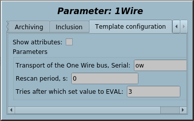
- Transport — to the address of the automatically created transport with its parameters after ":", according to the function SYS.Transport.outAt() address format, where the device address corresponds to the serial device with a DS9097 adaptor or the I2C device like to "/dev/i2c-1".
- Address of the I2C driver — in decimal number of address the I2C driver on the bus above and in range pointed in help to the field.
- Rescan period — periodicity of rescaning for new and removed devices search.
- Only add at scan — the sign of adding devices only at scan, that is preventing also their removing (mark of removed) at any wrong request on bad busses.
- Tries after which set value to EVAL — quantity of wrong tries before setting the attributes in EVAL.
- 4. RESULT: The logical parameter object will perform at first searching to 1Wire devices on the bus and creating included parameters to the each found one. Next the logical parameter object will perform gather data of the found devices and trace to modify of the writable device's properties.
5 I2C: PCF8591 (PCF8591) |
1.0 | GPLv2 | * | en | Roman Savochenko |
I2C 8-bit 4xA/D and D/A converter. Connects through a Serial output transport into the I2C mode.
Template IOs
| Identifier | Parameter | Type | Mode | Attribute | Configuration | Value |
|---|---|---|---|---|---|---|
| transport | Transport of the I2C, Serial | String | Input | Not attribute | Constant | i2c |
| addr | Device address [0...119] | Integer | Input | Not attribute | Constant | 72 |
| vRef | Reference voltage, V | Real | Input | Not attribute | Constant | 3.2 |
| ai0 | AI0 | Real | Input | Read only | Variable | |
| ai1 | AI1 | Real | Input | Read only | Variable | |
| ai2 | AI2 | Real | Input | Read only | Variable | |
| ai3 | AI3 | Real | Input | Read only | Variable | |
| ao | AO | Real | Input | Full access | Variable | |
| f_frq | Function calculate frequency (Hz) | Real | Input | Not attribute | Variable | 1000 |
| f_start | Function start flag | Boolean | Input | Not attribute | Variable | 0 |
| f_stop | Function stop flag | Boolean | Input | Not attribute | Variable | 0 |
| f_err | Function error | String | Input | Not attribute | Variable | 0 |
Configuring and using
- 1. Create an output transport of the type "Serial" and set its Identifier like to "i2c", one for each the I2C bus.
- 2. Set proper address of the Serial device, only the I2C bus address like "/dev/i2c-{N}". Set the symbol's time into the timeouts field to the minimum value.
- 3. Create and start a logical controller object or use any presented one with the needed scheduling properties.
- 4. Create a logical parameter object and select the template for that, one for each I2C slave devices. Enable the parameter.
- 5. Into the tab "Template configuration" of the logical parameter object you need to set:
- transport — to the address of the transport into step 1. Tracing for the address changing is supported.
- addr — the I2C slave device's address [0...119].
- vRef — reference voltage of the AIs and AO.
- 6. RESULT: The logical parameter object will perform interaction and placing of gathered data to the AI attributes and also will take the AO and write to the chip.
6 I2C: PCF8574 (PCF8574) |
1.0 | GPLv2 | * | en | Roman Savochenko |
I2C 8-bit 8DIO. Connects through a Serial output transport into the I2C mode.
Template IOs
| Identifier | Parameter | Type | Mode | Attribute | Configuration | Value |
|---|---|---|---|---|---|---|
| transport | Transport I2C | String | Input | Not attribute | Constant | i2c |
| addr | Device address (0, 119) | Integer | Input | Not attribute | Constant | 39 |
| di0 | DI0 | Boolean | Input | Read only | Variable | |
| di1 | DI1 | Boolean | Input | Read only | Variable | |
| di2 | DI2 | Boolean | Input | Read only | Variable | |
| di3 | DI3 | Boolean | Input | Read only | Variable | |
| di4 | DI4 | Boolean | Input | Read only | Variable | |
| di5 | DI5 | Boolean | Input | Read only | Variable | |
| di6 | DI6 | Boolean | Input | Read only | Variable | |
| di7 | DI7 | Boolean | Input | Read only | Variable | |
| do0 | DO0 | Boolean | Output | Full access | Variable | |
| do1 | DO1 | Boolean | Output | Full access | Variable | |
| do2 | DO2 | Boolean | Output | Full access | Variable | |
| do3 | DO3 | Boolean | Output | Full access | Variable | |
| do4 | DO4 | Boolean | Output | Full access | Variable | |
| do5 | DO5 | Boolean | Output | Full access | Variable | |
| do6 | DO6 | Boolean | Output | Full access | Variable | |
| do7 | DO7 | Boolean | Output | Full access | Variable | |
| f_frq | Function calculate frequency (Hz) | Real | Input | Not attribute | Variable | 1000 |
| f_start | Function start flag | Boolean | Input | Not attribute | Variable | 0 |
| f_stop | Function stop flag | Boolean | Input | Not attribute | Variable | 0 |
| f_err | Function error | String | Input | Not attribute | Variable | 0 |
Configuring and using
- 1. Create an output transport of the type "Serial" and set its Identifier like to "i2c", one for each the I2C bus.
- 2. Set proper address of the Serial device, only the I2C bus address like "/dev/i2c-{N}". Set the symbol's time into the timeouts field to the minimum value.
- 3. Create and start a logical controller object or use any presented one with the needed scheduling properties.
- 4. Create a logical parameter object and select the template for that, one for each I2C slave devices. Enable the parameter.
- 5. Into the tab "Template configuration" of the logical parameter object you need to set:
- transport — to the address of the transport into step 1. Tracing for the address changing is supported.
- addr — the I2C slave device's address [0...119].
- 6. RESULT: The logical parameter object will perform interaction and placing of gathered data to the DI attributes and also will take the DO and write to the chip.
7 I2C: ADS101x, ADS111x (ADS111x) |
1.0 | GPLv2 | * | en | Roman Savochenko |
I2C 12/16-bit 4xA/D converter. Connect through a Serial output transport into the I2C mode.
Template IOs
| Identifier | Parameter | Type | Mode | Attribute | Configuration | Value |
|---|---|---|---|---|---|---|
| transport | Transport of the I2C, Serial | String | Input | Not attribute | Constant | i2c |
| addr | Device address [0...119] | Integer | Input | Not attribute | Constant | 72 |
| range | Range, ±V | Integer numbers selection | Input | Full access | Variable | 2 0;1;2;3;4;5 |
| ai0 | AI0 | Real | Input | Read only | Variable | |
| ai1 | AI1 | Real | Input | Read only | Variable | |
| ai2 | AI2 | Real | Input | Read only | Variable | |
| ai3 | AI3 | Real | Input | Read only | Variable | |
| f_frq | Function calculate frequency (Hz) | Real | Input | Not attribute | Variable | 1000 |
| f_start | Function start flag | Boolean | Input | Not attribute | Variable | 0 |
| f_stop | Function stop flag | Boolean | Input | Not attribute | Variable | 0 |
| f_err | Function error | String | Input | Not attribute | Variable | 0 |
Configuring and using
- 1. Create an output transport of the type "Serial" and set its Identifier like to "i2c", one for each the I2C bus.
- 2. Set proper address of the Serial device, only the I2C bus address like "/dev/i2c-{N}". Set the symbol's time into the timeouts field to the minimum value.
- 3. Create and start a logical controller object or use any presented one with the needed scheduling properties.
- 4. Create a logical parameter object and select the template for that, one for each I2C slave devices. Enable the parameter.
- 5. Into the tab "Template configuration" of the logical parameter object you need to set:
- transport — to the address of the transport into step 1. Tracing for the address changing is supported.
- addr — the I2C slave device's address [0...119].
- range — range of voltage of the AIs.
- 6. RESULT: The logical parameter object will perform interaction and placing of gathered data to the AI attributes.
8 I2C: MCP4725 (MCP4725) |
1.0 | GPLv2 | * | en | Roman Savochenko |
I2C 12-bit D/A converter. Connect through a Serial output transport into the I2C mode.
Template IOs
| Identifier | Parameter | Type | Mode | Attribute | Configuration | Value |
|---|---|---|---|---|---|---|
| transport | Transport of the I2C, Serial | String | Input | Not attribute | Constant | i2c |
| addr | Device address [0...119] | Integer | Input | Not attribute | Constant | 96 |
| vRef | Reference voltage, V | Real | Input | Not attribute | Constant | 3.2 |
| ao | AO | Real | Input | Full access | Variable | |
| f_frq | Function calculate frequency (Hz) | Real | Input | Not attribute | Variable | 1000 |
| f_start | Function start flag | Boolean | Input | Not attribute | Variable | 0 |
| f_stop | Function stop flag | Boolean | Input | Not attribute | Variable | 0 |
| f_err | Function error | String | Input | Not attribute | Variable | 0 |
Configuring and using
- 1. Create an output transport of the type "Serial" and set its Identifier like to "i2c", one for each the I2C bus.
- 2. Set proper address of the Serial device, only the I2C bus address like "/dev/i2c-{N}". Set the symbol's time into the timeouts field to the minimum value.
- 3. Create and start a logical controller object or use any presented one with the needed scheduling properties.
- 4. Create a logical parameter object and select the template for that, one for each I2C slave devices. Enable the parameter.
- 5. Into the tab "Template configuration" of the logical parameter object you need to set:
- transport — to the address of the transport into step 1. Tracing for the address changing is supported.
- addr — the I2C slave device's address [0...119].
- vRef — reference voltage of the AO.
- 6. RESULT: The logical parameter object will perform interaction and take the AO and write to the chip.
9 I2C: BMP180 (BMP180) |
1.0 | GPLv2 | * | en | Roman Savochenko |
I2C Pressure and Temperature sensor. Connecting through a Serial output transport into the I2C mode.
Template IOs
| Identifier | Parameter | Type | Mode | Attribute | Configuration | Value |
|---|---|---|---|---|---|---|
| transport | Transport of the I2C, Serial | String | Input | Not attribute | Constant | i2c |
| addr | Device address [0...119] | Integer | Input | Not attribute | Constant | 119 |
| oss | Oversampling setting (0...3) | Integer | Input | Not attribute | Constant | 0 |
| t | T, °С | Real | Input | Read only | Variable | |
| p | P, Pa | Real | Input | Read only | Variable | |
| f_frq | Function calculate frequency (Hz) | Real | Input | Not attribute | Variable | 1000 |
| f_start | Function start flag | Boolean | Input | Not attribute | Variable | 0 |
| f_stop | Function stop flag | Boolean | Input | Not attribute | Variable | 0 |
| f_err | Function error | String | Input | Not attribute | Variable | 0 |
Configuring and using
- 1. Create an output transport of the type "Serial" and set its Identifier like to "i2c", one for each the I2C bus.
- 2. Set proper address of the Serial device, only the I2C bus address like "/dev/i2c-{N}". Set the symbol's time into the timeouts field to the minimum value.
- 3. Create and start a logical controller object or use any presented one with the needed scheduling properties.
- 4. Create a logical parameter object and select the template for that, one for each I2C slave devices. Enable the parameter.
- 5. Into the tab "Template configuration" of the logical parameter object you need to set:
- transport — to the address of the transport into step 1. Tracing for the address changing is supported.
- addr — the I2C slave device's address [0...119].
- oss — oversampling setting of pressure measurement [0...3].
- 6. RESULT: The logical parameter object will perform interaction and placing of gathered data to the Pressure and Temperature attributes.
10 I2C: BME280 (BME280) |
1.0 | GPLv2 | * | en | Arcadiy Kisel, Roman Savochenko |
I2C Barometric Pressure, Temperature and Humidity sensor. Connect through a Serial output transport into the I2C mode.
Template IOs
| Identifier | Parameter | Type | Mode | Attribute | Configuration | Value |
|---|---|---|---|---|---|---|
| transport | Transport of the I2C, Serial | String | Input | Not attribute | Constant | i2c |
| addr | Device address [0...119] | Integer | Input | Not attribute | Constant | 118 |
| oss | Oversampling setting (0...7) | Integer | Input | Not attribute | Constant | 0 |
| t | T, °С | Real | Input | Read only | Variable | |
| p | P, Pa | Real | Input | Read only | Variable | |
| h | H, % | Real | Input | Read only | Variable | |
| f_frq | Function calculate frequency (Hz) | Real | Input | Not attribute | Variable | 1000 |
| f_start | Function start flag | Boolean | Input | Not attribute | Variable | 0 |
| f_stop | Function stop flag | Boolean | Input | Not attribute | Variable | 0 |
| f_err | Function error | String | Input | Not attribute | Variable | 0 |
Configuring and using
- 1. Create an output transport of the type "Serial" and set its Identifier like to "i2c", one for each the I2C bus.
- 2. Set proper address of the Serial device, only the I2C bus address like "/dev/i2c-{N}". Set the symbol's time into the timeouts field to the minimum value.
- 3. Create and start a logical controller object or use any presented one with the needed scheduling properties.
- 4. Create a logical parameter object and select the template for that, one for each I2C slave devices. Enable the parameter.
- 5. Into the tab "Template configuration" of the logical parameter object you need to set:
- transport — to the address of the transport into step 1. Tracing for the address changing is supported.
- addr — the I2C slave device's address [0...119].
- oss — oversampling setting of pressure measurement [0...7].
- 6. RESULT: The logical parameter object will perform interaction and placing of gathered data to the Pressure, Temperature and Humidity attributes.
11 I2C: SHT3x (SHT3x) |
1.0 | GPLv2 | * | en | Roman Savochenko |
Digital Temperature and Humidity Sensor for the models: SHT30
Template IOs
| Identifier | Parameter | Type | Mode | Attribute | Configuration | Value |
|---|---|---|---|---|---|---|
| transport | Transport of the I2C, Serial | String | Input | Not attribute | Constant | i2c |
| addr | Device address [0...119] | Integer | Input | Not attribute | Constant | 68 |
| H | Humidity | Real | Input | Read only | Variable | |
| T | Temperature | Real | Input | Read only | Variable | |
| f_frq | Function calculate frequency (Hz) | Real | Input | Not attribute | Variable | 1000 |
| f_start | Function start flag | Boolean | Input | Not attribute | Variable | 0 |
| f_stop | Function stop flag | Boolean | Input | Not attribute | Variable | 0 |
| f_err | Function error | String | Input | Not attribute | Variable | 0 |
Configuring and using
- 1. Create an output transport of the type "Serial" and set its Identifier like to "i2c", one for each the I2C bus.
- 2. Set proper address of the Serial device, only the I2C bus address like "/dev/i2c-{N}". Set the symbol's time into the timeouts field to the minimum value.
- 3. Create and start a logical controller object or use any presented one with the needed scheduling properties.
- 4. Create a logical parameter object and select the template for that, one for each I2C slave devices. Enable the parameter.
- 5. Into the tab "Template configuration" of the logical parameter object you need to set:
- transport — to the address of the transport into step 1. Tracing for the address changing is supported;
- addr — the I2C slave device's address [0...119].
- 6. RESULT: The logical parameter object will perform interaction and placing of gathered data to the Temperature and Humidity attributes.
12 I2C: DS1307,DS3231 (DS3231) |
1.1 | GPLv2 | * | en | Roman Savochenko |
I2C RTC chips DS1307,DS3231 with Temperature sensor and calibration for DS3231. Connects through a Serial output transport into the I2C mode.
Template IOs
| Identifier | Parameter | Type | Mode | Attribute | Configuration | Value |
|---|---|---|---|---|---|---|
| transport | Transport of the I2C, Serial | String | Input | Not attribute | Constant | i2c |
| addr | Device address [0...119] | Integer | Input | Not attribute | Constant | 119 |
| mode | Mode | Integer numbers selection | Input | Full access | Variable | 0
0;1 |
| tm | Date and time, YYYY-MM-DDTHH:mm:SS | String | Input | Full access | Variable | |
| pSQW | Enable SQUARE-WAVE OUTPUT | Boolean | Input | Full access | Variable | |
| pSQWf (dynamically updated) |
SQUARE-WAVE OUTPUT frequency | Integer | Input | Full access | Variable | |
| agOff (dynamically created for DS3231) |
Aging offset, [-128...127] | Integer | Input | Full access | Variable | |
| t (dynamically created for DS3231) |
T, °С | Real | Input | Read only | Variable | |
| p32k (dynamically created for DS3231) |
Enable 32768Hz | Boolean | Input | Full access | Variable | |
| f_frq | Function calculate frequency (Hz) | Real | Input | Not attribute | Variable | 1000 |
| f_start | Function start flag | Boolean | Input | Not attribute | Variable | 0 |
| f_stop | Function stop flag | Boolean | Input | Not attribute | Variable | 0 |
| f_err | Function error | String | Input | Not attribute | Variable | 0 |
Configuring and using
- 1. Create an output transport of the type "Serial" and set its Identifier like to "i2c", one for each the I2C bus.
- 2. Set proper address of the Serial device, only the I2C bus address like "/dev/i2c-{N}". Set the symbol's time into the timeouts field to the minimum value.
- 3. Create and start a logical controller object or use any presented one with the needed scheduling properties.
- 4. Create a logical parameter object and select the template for that, one for each I2C slave devices. Enable the parameter.
- 5. Into the tab "Template configuration" of the logical parameter object you need to set:
- transport — to the address of the transport into step 1. Tracing for the address changing is supported.
- addr — the I2C slave device's address [0...119].
- 6. RESULT: The logical parameter object will perform interaction and placing of gathered data to the DateTime, Temperature and some one state attributes and also will take the DateTime, some one state attributes and write it to the chip.
13 I2C: AT24C{32|64} (AT24CXX) |
1.0 | GPLv2 | * | en | Roman Savochenko |
Provides operations with EEPROM memory based on I2C chips AT24C32 (4KB) and AT24C64 (8KB). Supported random reading and writing.
Output user protocol's XML request structure
<{cmd} addr="{ChipAddr}" off="{MemOffset}" size="{ReadSize}" err="1:Error">{ReadWriteSeq}</{cmd}>
- cmd — command, for now there allowed: "read", "write";
- addr — I2C device address [0...119];
- off — memory part offset;
- size — read memory block size.
- ReadWriteSeq — Read/Write bytes sequence.
- err — sets to result of the request.
Configuring and using
- 1. Create an output transport of the type "Serial" and set its Identifier like to "i2c", one for each the I2C bus.
- 2. Set proper address of the Serial device, only the I2C bus address like "/dev/i2c-{N}". Set the symbol's time into the timeouts field to the minimum value.
- 3. Place some requesting commands directly into presented or a new internal OpenSCADA procedure like to:
req = SYS.XMLNode("read"); req.setAttr("ProtIt","AT24CXX").setAttr("addr",87).setAttr("off",1000).setAttr("size",20).setText("My message");
req = SYS.XMLNode("write"); req.setAttr("ProtIt","AT24CXX").setAttr("addr",87).setAttr("off",1000).setText("Stored data");
- 4. RESULT: Into text() for "read" you will get the read data if no errors occur.
14 GPIO: DHT11,22 (DHT) |
1.0 | GPLv2 | * | en | Roman Savochenko |
Digital Temperature and Humidity Sensor for models: DHT11, DHT12, AM2302, AM2320, ... . The module designed for the sensors connect through GPIO, mostly it's Raspberry PI BCM2835 GPIO.
Conditions: Exclusively realtime planing in the priority 199 (FIFO-99).
Template IOs
| Identifier | Parameter | Type | Mode | Attribute | Configuration | Value |
|---|---|---|---|---|---|---|
| addr | GPIO address with functions mode(), get() and put(), mostly it's BCM2835 | String | Input | Not attribute | Constant | DAQ.GPIO.io.pi |
| pin | IO pin number of the GPIO | Integer | Input | Not attribute | Constant | 17 |
| tries | Tries [1...5] | Integer | Input | Not attribute | Constant | 2 |
| dev | Device (0-DHT11, 1-DHT22) | Integer | Input | Not attribute | Constant | 1 |
| t | T, °С | Real | Input | Read only | Variable | |
| h | H, % | Real | Input | Read only | Variable | |
| f_frq | Function calculate frequency (Hz) | Real | Input | Not attribute | Variable | 1000 |
| f_start | Function start flag | Boolean | Input | Not attribute | Variable | 0 |
| f_stop | Function stop flag | Boolean | Input | Not attribute | Variable | 0 |
| f_err | Function error | String | Input | Not attribute | Variable | 0 |
Configuring and using
- 1. Create an output controller object and a parameter into the DAQ module "BCM 2835", by default it's "pi.pi".
- 2. Create and start a logical controller object or use any presented one with the needed scheduling properties (FIFO-199).
- 3. Create a logical parameter and select the template for that, one for each sensor. Enable the parameter.
- 4. Into the tab "Template configuration" of the logical parameter object you need to set:
- addr — to the address of the "BCM 2835" parameter like "DAQ.GPIO.io.pi"; tracing for the address changing is supported;
- pin — GPIO pin number where connected the data pin of the sensor;
- tries — tries of the sensor reading;
- dev — generic device specific selection.
- 5. RESULT: The logical parameter will perform interaction and placing of the gathered data to the Temperature and Humidity attributes.
15 GPIO: MAX6675 (MAX6675) |
0.1 | GPLv2 | * | en | Arcadiy Kisel |
Cold-Junction-Compensated K-Thermocouple-to-Digital Converter (0°C to +1024°C). The module designed for the sensors connect through softSPI by GPIO, mostly it's Raspberry PI BCM2835 GPIO.
Conditions: Exclusively realtime planing in the priority 199 (FIFO-99).
Template IOs
| Identifier | Parameter | Type | Mode | Attribute | Configuration | Value |
|---|---|---|---|---|---|---|
| addr | GPIO address with functions mode(), get() and put(), mostly it's BCM2835 | String | Input | Not attribute | Constant | DAQ.GPIO.io.pi |
| pin_cs | CS pin number of the GPIO | Integer | Input | Not attribute | Constant | 8 |
| pin_sclk | SCLK pin number of the GPIO | Integer | Input | Not attribute | Constant | 11 |
| pin_miso | MISO pin number of the GPIO | Integer | Input | Not attribute | Constant | 9 |
| t | T, °С | Real | Output | Read only | Variable | |
| f_frq | Function calculate frequency (Hz) | Real | Input | Not attribute | Variable | 1000 |
| f_start | Function start flag | Boolean | Input | Not attribute | Variable | 0 |
| f_stop | Function stop flag | Boolean | Input | Not attribute | Variable | 0 |
| f_err | Function error | String | Input | Not attribute | Variable | 0 |
Configuring and using
- 1. Create an output controller object and a parameter into the DAQ module "BCM 2835", by default it's "pi.pi".
- 2. Create and start a logical controller object or use any presented one with the needed scheduling properties (FIFO-199).
- 3. Create a logical parameter and select the template for that, one for each sensor. Enable the parameter.
- 4. Into the tab "Template configuration" of the logical parameter object you need to set:
- addr — to the address of the "BCM 2835" parameter like "DAQ.GPIO.io.pi"; tracing for the address changing is supported;
- pin_cs — CS pin number where connected the chip selection pin of the sensor;
- pin_sclk — SCLK pin number where connected the serial clock pin of the sensor;
- pin_miso — MISO pin number where connected the master in slave out (data) pin of the sensor.
- 5. RESULT: The logical parameter will perform interaction and placing of the gathered data to the Temperature attributes.
16 GPIO|I2C: 1602A(HD44780) (1602A) |
1.0 | GPLv2 | * | en | Roman Savochenko |
LCD Module 1602A, STN, BLUB, 16 Character x 2 Line, 5 x 8 Dots, by the direct (Raspberry PI BCM2835 GPIO) or I2C (PCF8574) wiring.
Conditions: Default planing policy but realtime one preferred.
Template IOs
| Identifier | Parameter | Type | Mode | Attribute | Configuration | Value |
|---|---|---|---|---|---|---|
| transport | Transport of the I2C, Serial (i2c) or GPIO address with function put(), mostly it's BCM2835 (DAQ.GPIO.io.pi) |
String | Input | Not attribute | Constant | i2c |
| addr | I2C device address [0...119] | Integer | Input | Not attribute | Constant | 39 |
| RS | GPIO Pin: Reset | Integer | Input | Not attribute | Constant | 7 |
| E | GPIO Pin: Enable | Integer | Input | Not attribute | Constant | 8 |
| D4 | GPIO Pin: Data4 | Integer | Input | Not attribute | Constant | 25 |
| D5 | GPIO Pin: Data5 | Integer | Input | Not attribute | Constant | 24 |
| D6 | GPIO Pin: Data6 | Integer | Input | Not attribute | Constant | 23 |
| D7 | GPIO Pin: Data7 | Integer | Input | Not attribute | Constant | 18 |
| ln1 | Line 1 | String | Input | Full access | Variable | |
| ln2 | Line 2 | String | Input | Full access | Variable | |
| f_frq | Function calculate frequency (Hz) | Real | Input | Not attribute | Variable | 1000 |
| f_start | Function start flag | Boolean | Input | Not attribute | Variable | 0 |
| f_stop | Function stop flag | Boolean | Input | Not attribute | Variable | 0 |
| f_err | Function error | String | Input | Not attribute | Variable | 0 |
Configuring and using
- 1. Create an output controller and an object of parameter in DAQ module "BCM 2835", by default it's "pi.pi" or create an output transport of the type "Serial", set address like to "i2c", one for each the I2C bus.
- 2. Create and start a logical controller object or use any presented one with the needed scheduling properties.
- 3. Create a logical parameter object and select the template for that, one for each sensor. Enable the parameter.
- 4. Into the tab "Template configuration" of the logical parameter object you need to set:
- transport — to address of the "BCM 2835" parameter like to "DAQ.GPIO.io.pi" or to address of the transport into step 1; tracing for the address changing is supported;
- addr — the I2C slave device's address [0...119];
- RS, E, D4, D5, D6, D7 — numbers of the GPIO pins where connected the proper data ones of the sensor.
- 5. RESULT: The logical parameter object will perform interaction and setting lines' values to the display.

