- Author: Roman Savochenko
Maxim Lysenko (2012) — the page initial translation - Initially created: in the old Wiki
This document is a manual of the "open source" program called "OpenSCADA". OpenSCADA represents a SCADA system built on the principles of modularity, multiplatformity and scalability.
As a policy of the development of the program there uses "open source" principle. This choice was done at needs of creation of a free, reliable and publicly available SCADA system. This policy allows to bring together a significant number of developers, enthusiasts and other interested persons to develop, test, improve, distribute and use the program, thus minimizing and distribution of efforts and financial costs.
OpenSCADA is designed for acquisition, archiving, visualization of information, performing of control actions and for other related operations charactered for full-featured SCADA systems. Due to the high level of abstraction and modularization the program can be used in a variety of related industries.
OpenSCADA can be and used now at:
- industrial facilities as a full featured SCADA system or telemechanics;
- dynamic models, imitators and training apparatus of technological processes into the real-time;
- machine tools and industrial robots;
- agricultural dispatching and control systems, poultry-yards;
- embedded and mobile systems — environments of execution Programming Logical Controllers (PLC), robots, ...;
- server equipment monitoring;
- smart houses and home automation.
In the role of the common operating system (program platform) for development and using there was selected Linux OS, which is an optimal solution of the following issues:
- reliability — a large part of servers and clusters running on GNU/Linux OS;
- flexibility/scalability — due to its openness and modularity Linux allows to build solutions to meet any requirements;
- availability — due to being under the license GPL the software is a fully free (libre) operational system and for high qualified users it can be also a non-cost one;
- popularity, advancement, support and prevalence — the system is in active development by many enthusiasts, firms and government agencies throughout the world, and is gaining wide support on the personal and the corporate marketplace.
While the project currently develops under the principles of multiplatformity then there is no most problem for porting the project to other operational systems (program platforms) and hardware platforms. That is planned to future and mostly already done for some platforms.
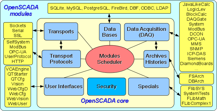
At the heart of the program is a modular core. And depending on what modules are installed the program can be configured to operate in role of variety servers, clients and both clients and servers in the same time and into the same program. It allows for implementation of the client-server architecture on the same components/modules, saving machine memory, disk space and expensive programming time.
Server configurations of the program were designed for issuing control actions and acquisition, processing, archiving, logging information from different sources and this information providing also to clients (UI, GUI, TUI ...). The modular architecture allows for expanding of server's functionality without it restarting.
Client configurations can be built on different graphics libraries (GUI/TUI ToolKits), as using the program core and its modules (by adding to it an user interface module), or as an independent application connected the OpenSCADA core as a library.
The flexible configuration of the program allows for user to build solutions to meet specific requirements of reliability, functionality and capacity-complexity.
Contents
- 1 Architecture and functions
- 1.1 Modularity
- 1.2 Subsystems
- 1.3 PLC and other sources of dynamic data, the subsystem "Data acquisition"
- 1.4 Databases, the subsystem of "Databases"
- 1.5 Archives and history, the subsystem "Archives-History"
- 1.6 Communications, the subsystem "Transports" and "Transport protocols"
- 1.7 User interfaces, the subsystem "User Interfaces"
- 1.8 Security of the program, the subsystem "Security"
- 1.9 Management of modules, the subsystem "Modules scheduler"
- 1.10 Unforeseen opportunities, the subsystem "Specials"
- 1.11 Functions, object model and programming environment of the user
- 2 SCADA systems and their structure
- 3 Ways of configuration and using
- 3.1 Simple server connection
- 3.2 Duplicated server connection
- 3.3 Duplicated server connection on one server
- 3.4 Client access by means of the Web-interface. A place of the manager
- 3.5 Automated workplace (place of the manager/operator)
- 3.6 AWP with a server of acquisition and archiving on single machine (place of the operator, simulator ...)
- 3.7 Elementary mixed connection (simulator, demonstration, configurator ...)
- 3.8 Robust Distributed Configuration
- 4 Configuration and settings
- 4.1 Subsystem "DB"
- 4.2 Subsystem "Security"
- 4.3 Subsystem "Transports"
- 4.4 Subsystem "Transport protocols"
- 4.5 Subsystem "Data acquisition"
- 4.6 Subsystem "Archives-History"
- 4.7 Subsystem "User interfaces"
- 4.8 Subsystem "Specials"
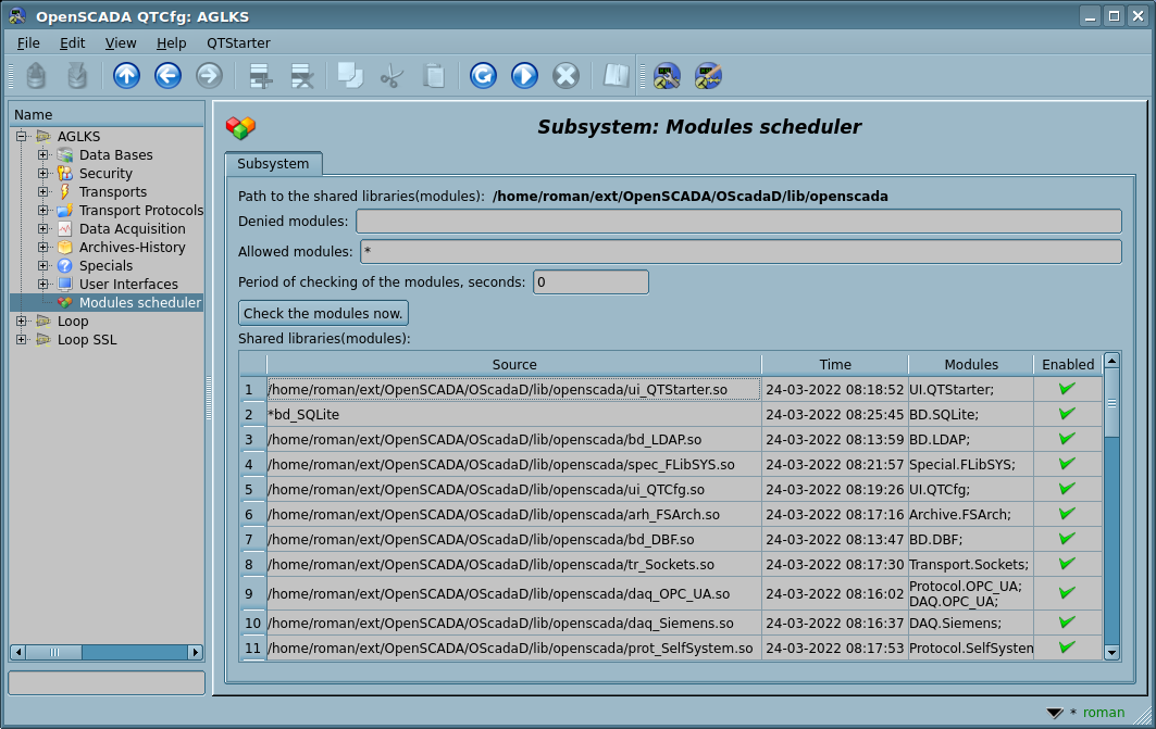
- 4.9 Subsystem "Modules scheduler"
- 4.10 Configuration File and command line parameters
- 5 Startup and execution
- 6 Links
1 Architecture and functions
About actual functions and demands of OpenSCADA you can read on the page "Functions and demands" but in this document we will learn the common functions and properties of the program.
1.1 Modularity
In order to achieve flexibility and a high degree of scalability OpenSCADA is constructed in a modular fashion. Tight integration the modules with the core improves the program stability in whole due to repeat of using the well-tuned code. But same process of developing of self code of the modules OpenSCADA imposes greater responsibility — possible errors introduce an element of instability into the program. The ability to create distributed configurations smooths this danger.
OpenSCADA modules are stored within dynamic libraries and each shared library can contain modules of various types. The filling of dynamic libraries by modules is determined by the functional connectivity of the modules itself. Dynamic libraries are hot swappable which allows to update certain parts of the program during the operation. This method of storing of modules' code in dynamic libraries is essential for OpenSCADA, because it is supported by practically all modern operating systems (OS). However, this does not exclude the possibility of developing other methods of storing of the modules' code.
OpenSCADA has the following functional parts implemented in modules:
- databases;
- communication interfaces, transports;
- protocols of the communication interfaces;
- data sources and data acquisition;
- archives-history (messages and values);
- user interfaces (GUI, TUI, WebGUI, speech, signal ...);
- additional modules, special.
Management of the modules is carried out by the "Module scheduler" subsystem. The subsystem functions are: connection, switching off, updating and other operations concerned with the modules and their libraries.
1.2 Subsystems
Architecturally OpenSCADA is divided into subsystems. Subsystems can be two types: regular and modular. Modular subsystem have the ability of expanding by modules. Each the modular subsystem can contain many of modular objects. For example, the modular subsystem "Databases" contains modular objects of types of databases. Modular object is the root of the module.
Summary OpenSCADA contains nine subsystems with seven being modular. These nine subsystems of OpenSCADA are base ones and their present at every configuration. To the list of these nine subsystems can be added new ones, through the modules themselves. OpenSCADA subsystems:
- Security.
- Modules Scheduler.
- Data Bases (modular).
- Transports (modular).
- Transport Protocols (modular).
- Data Acquisition (modular).
- Archives-Histories (modular).
- User Interfaces (modular).
- Specials (modular).
1.3 PLC and other sources of dynamic data, the subsystem "Data acquisition"
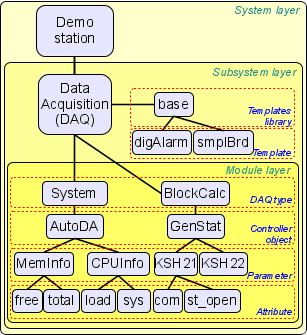
The subsystem "DAQ" (Data Acquisition) (Fig.1.3) provides to support dynamic data sources whether: PLC, MOD, virtual sources and other. The function of this subsystem is to provide the received data in structured form — the data model and to provide management of these data, for example, these are data modification.
The subsystem "DAQ" is a modular one and it contains modular objects of types of sources of dynamic data. For example, OpenSCADA provides now more than twenty modules and library items by sources of the logical level. Most significant and developed from them are:
- Java-like based calculator;
- Logical level;
- Block calculator;
- Gateway of the data sources;
- System DA;
- ModBus;
- DCON client;
- Client OPC-UA;
- Siemens DAQ;
- MMS(IEC-9506);
- SNMP client;
- ICP DAS hardware;
- Diamond DAQ boards.
Each non-logical source type is implemented into a separate module, which can contain many sources (controller objects), and each source is usually executed in a separate thread-task.
Separately taken object controller may contain parameters specified by module types. For example, the parameters of the analog type, the basic information of which is the value of the integer or the real type. Structurally, the parameter is a list of attributes that contain data. Attributes can have five basic types: logical, integer, real, character string (text) and object. Structures of controller objects, parameters and their types are contained in the subsystem "DAQ" so that the module objects carry out their filling in accordance with their own specifics.
Certain types of data sources themselves can generate data as they generate them entirely, as well as processing physical data, and even fully implement the gathering of these data into OpenSCADA environment and its internal language. Such data sources are called logical. Fully logical data sources are represented by modules: LogicLev and BlockCalc. There are several modules that combine logical data as a result of direct physical ones processing: ModBus, Siemens and OPC-UA.
Dynamic data sources can be remote, that is, they can be generated or received at the remote OpenSCADA station. To communicate with such data sources, the DAQGate gateway module is used. The function of this type of data sources is to display the data sources of the remote OpenSCADA station to the local one.
You can read in detail the key subsystem "DAQ" and its functions in a separate document "Data acquisition in OpenSCADA".
1.4 Databases, the subsystem of "Databases"
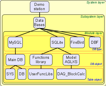
To store data of the program are constantly used databases (DB). In order to unify access and manage databases, OpenSCADA has a subsystem called "Databases" (Fig.1.4). To support different DB/DBMS the subsystem implemented as a modular one.
In the role of modular object contained in the subsystem, the type of DB/DBMS acts, that is, any module of the subsystem "Databases" practically contain the implementation of access to a specific type of database. OpenSCADA provides that most significant and developed modules: SQLite, MySQL, PostgreSQL, FireBird.
Type of the DB/DBMS in its turn contains a list of objects of separate DB of this type, and the database object contains a list of table objects, which contain data in tabular form.
Practically all OpenSCADA data is stored in one or another database. The program's toolkit allows you to easily transfer data from one type of database to another, and, as a result, optimally select a database type for a specific scope of application OpenSCADA. Transferring information from one database to another can be done in two ways. The first one is to change the address of the working DB and to save the whole configuration of the program to it, the second one — it is direct copying information between the database. Except of copying the function of direct editing of content of tables of DB is supported also.
There are two ways to organize the centralized access of a distributed program to a single database. The first is the use of network databases, for example — MySQL. The second way is to use a transport type database on local stations to access one central database of another OpenSCADA station, by sending requests to the database at that remote station — not yet implemented in OpenSCADA.
Data can also be stored in the configuration file of the program. The mechanism of full mapping of the DB structure to the structure of the configuration file is implemented. That is, the standard configuration can be placed in the configuration file. The essence of the mechanism is that the typical (by default) data of programs can be described in the configuration file, for example — when starting without a DB. In the future, these data can be redefined in the DB. In addition, for cases of impossibility to run any DB in general, all data can be stored in the configuration file.
To access databases, a DB registration mechanism is used. Registered DBs in the program are accessible to all OpenSCADA subsystems and can be used in their work. Thanks to this mechanism, you can ensure the distribution of data storage. For example, different libraries can be stored and distributed independently, and connecting a library will be simple registration of the desired DB.
1.5 Archives and history, the subsystem "Archives-History"
Any SCADA system should provide the ability to archive the gathered data, that is, to form the history of the change (dynamics) of the process. Archives can be divided into two types: messages and values archives.
The peculiarity of message archives is the very archiving of so-called program messages, that is logging. A characteristic sign of a message is the time of its occurrence. Depending on the source the messages can be classified according to different criteria. For example, it can be emergency reports, operator logs, communication failure protocols, and more.
The peculiarity of the value archives is their periodicity, which is determined by the time interval between two adjacent values. Value archives are used to archive the history of continuous processes. Since the process is continuous, it can be archived only by introducing the concept of quantization of the acquired values, otherwise we will receive archives of infinite sizes, in accordance with the continuity of the nature of the process itself. Besides, we can practically get values with a period limited by the data sources themselves. For example, rather high-quality data sources in industry rarely allow data to be received at frequencies above 1 kHz, without taking into account the sensors themselves, which have less qualitative frequency characteristics.
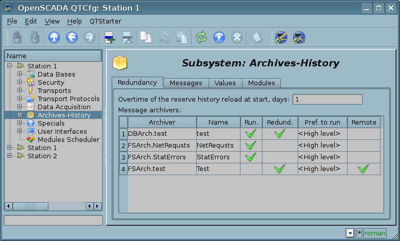
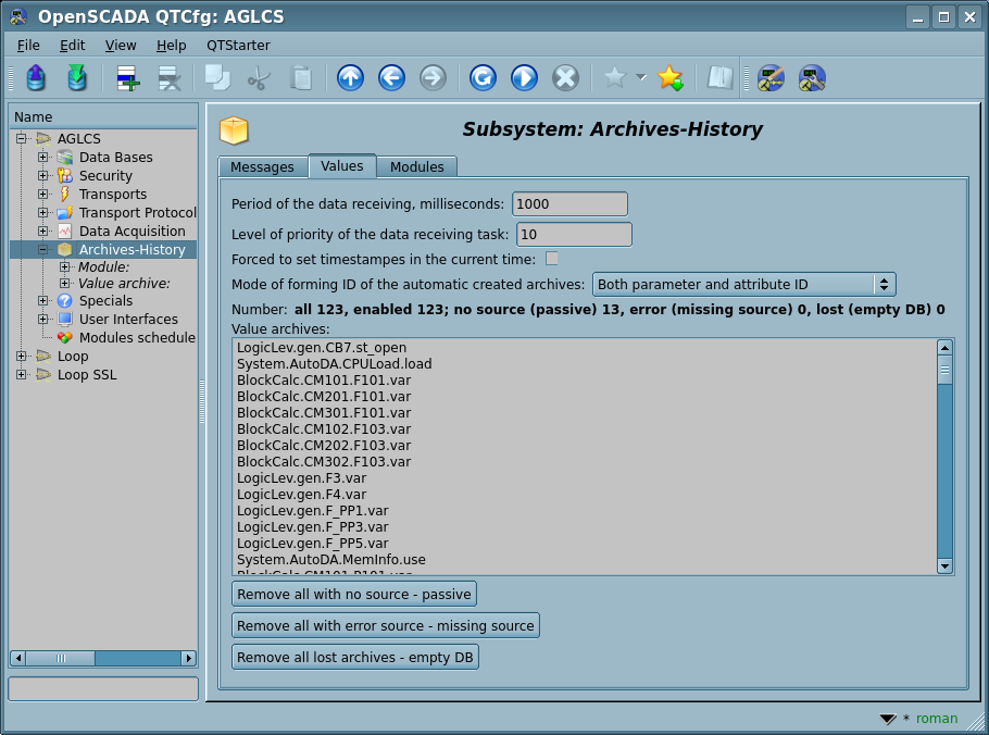
To solve the problems of archiving data streams in OpenSCADA provides a subsystem "Archives-History" (Fig.1.5), which is modular and allows you to maintain archives of messages and values. Modular object, which is contained in the subsystem "Archives-History", is the type of archiver. The type of archiver determines a way of data storing ie the storage — file system, DBMS. Each module of the "Archives-History" subsystem, respectively, can implement the archiving of messages and values, and the subsystem itself can contain many archives that are processed by different modules.
1.5.1 Messages
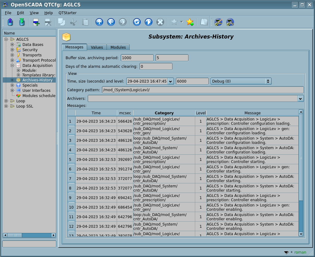
Messages in OpenSCADA are characterized by the date, level of importance, category, and directly the message text. Date of a message indicates the date and time of his creation. Level of importance points to importance of the message. Category defines address or identifier-key of the message source. Often, category contains full path to a source of the message in the program. Text of a message, respectively, has the main meaning of the message.
When archiving messages, they are passed through a filter that works according to importance level and category of messages. Messages level in a filter indicates that you must skip messages with specified or higher levels of importance. For filtering by category, templates or regular expressions are used to determine which messages to pass. Each archiver has its own filter settings, therefore, it is easy to create various specialized archivers for the archive of messages. For example, archivers of messages can be directed to:
- logs, to store debugging information and other working information of servers;
- different protocols (users action protocol, protocol of violations and exceptions, messages protocol ...).
There are 8 message levels, but each of these levels, from 1 (first), can be extended by sublevels, ie actually be a group of 10 sublevels by simply adding a number after the basic level, for example, 5 is the basic level and 50...59 is an extension of level 5. Which sets the total number of levels at 80. The seven main levels have names, and correspondence to what is desirable to follow:
- 0 — Debug;
- 1[X] — Information;
- 2[X] — Notice;
- 3[X] — Warning;
- 4[X] — Error;
- 5[X] — Critical;
- 6[X] — Alert;
- 7[X] — Emergency.
In accordance with the nature of messages and violations the subsystem "Archives-History" contains a buffer of current violations, which contains these most actual ones with category of the messages as the key-ID. Access to the buffer-list of current violations is done by indicating the negative value of the message level. Thus, formation of a message with a negative level -2 causes the location of this message in the buffer of active violations with level 2, as well as duplicate it directly in the message archive (the general messages buffer). At forming a message in the same category, but at a positive level — say 1, this violation will be removed from the buffer of violations, and the message will also fall into the message archive (the general messages buffer). Such a mechanism allows simultaneous accounting of active violations and logging of their passage in the message archive. When requesting an archive of messages, the definition of the positive level requests the archive of messages (through the general messages buffer), and the negative to the buffer-list of current violations.
The strict structure of the category and the text of the message is not intended, and the user can create them for their own messages arbitrarily, but account should be taken of the structure of system messages and messages defined by standard OpenSCADA libraries to prevent intersection with them, or targeting expanding:
- System, are generates by the OpenSCADA objects-nodes:
- CATEGORY: defines a typical path to the message node, for example — "/sub_DAQ/mod_LogicLev/cntr_gen/", where:
- "/*/*" — the typical template-sign of a system message based on a delimiter character of a path element that can be directly used in the category filter to determine only the system message archive.
- TEXT: contains the path of the name of the message node and the same message in the format "{NodeNmPath}: {message}", for example — "AGLKS > Data Acquisition > LogicLev > gen: Controller starting.".
- Transferred, messages that were received from the hierarchically lower stations of OpenSCADA (like PLC) or sent by the higher stations:
- CATEGORY: the controller object ID of the module DAQ.DAQGate is added to the start of the received message category, for example — "loop:alModBus:testTCP" or "TopStat(DAQCntr):alModBus:testTCP", where:
- "loop:*" — the typical template-sign of the remote lower messages based on the controller object identifier of the DAQ.DAQGate module that can be directly used in the category filter to determine only the remote message archive of this source;
- "TopStat(DAQCntr):*" — the typical template-sign of the remote higher messages based on the higher station project name (or ID) TopStat and the controller object identifier DAQCntr of the DAQ.DAQGate module that can be directly used in the category filter to determine only the remote message archive of this source.
- Unified structures with the DAQ-source in the category, are generated by the data source or its procedures using the function messSet() of the OpenSCADA API and the User API:
- CATEGORY: defines the ID-address of the source in the format "{ID}{ModId}:{CntrId}[.{PrmId}][:{SpecPrms}]", where:
- ID — two symbol structure identification;
- ModId — identifier of the module;
- CntrId — identifier of the controller object;
- PrmId — identifier of the parameter;
- SpecPrms — specific parameters of the structure ID.
- Violations, are generated by the data source or its procedures using the function alarmSet() of the OpenSCADA API and the User API:
- CATEGORY: defines the ID-address of the source in the format "al{ModId}:{CntrId}[.{PrmId}]", for example — "alLogicLev:gen.F_PP1", where:
- "al*" — the typical template-sign of a violation message based on the first two characters of the word "alarm", which can be directly used in the category filter to determine only the archive of violations.
- TEXT: "{CntrNm} > {PrmNm}: {MessText}", for example — "Mainstation > F_PP1: Gas flow through the diaphragm PP1: Upper warning border error", where:
- CntrNm — name of the controller object;
- PrmNm — name of the parameter.
- MessText — text of the message, which has the substructure "{Viol}: {Value}[: {QuietTime}[: {NormTime} [: {Comment}]]]", where:
- Viol — description of the violation, which some frames, such as Main.alarmsAct and Main.alarmsSt, can expand by custom fields in the form "[[{CustFld0} => {CustFld1} => ... => {CustFldN}]]";
- Value — value of the violation;
- QuietTime — quietance time;
- NormTime — time of return to the NORM-state, set here after quietation-acquiring already NORM message;
- Comment — commentary of the issue.
- User-operator actions with the DAQ-source, are generated by the widget procedures at the determined actions of the user-operator which must be recorded in the protocol of user-operator, and when the DAQ-parameter object is accessible:
- CATEGORY: defines the user and the complete characteristic DAQ-source for which actions are made, in the format "OP{ModId}:{CntrId}[.{PrmId}]:{user}", for example — "OPLogicLev:gen.PC_PCV1:roman", where:
- "OP*" — the typical pattern-sign of the user-operator action message based on the first two characters of the word "operator" that can be directly used in the category filter to determine only operator's archive of operations.
- TEXT: the same as the "User-operator actions" structure.
- CATEGORY: defines the ID-address of the source in the format "{ID}{ModId}:{CntrId}[.{PrmId}][:{SpecPrms}]", where:
- User-operator actions, are generated by the widget procedures at the determined actions of the user-operator, which must be recorded in the protocol of user-operator:
- CATEGORY: defines the user and the characteristic source (usually the DAQ-subsystem parameter) for which actions are made, in the format "OP:{user}:{src}", for example — "OP:roman:PC_PCV1", where:
- "OP:*" — the typical pattern-sign of the user-operator action message based on the first two characters of the word "operator" that can be directly used in the category filter to determine only operator's archive of operations;
- user — OpenSCADA user;
- src — characteristic source, usually the parameter of the subsystem "Data acquisition", if necessary, supplemented by a hierarchy of DAQ-parameters up to the controller object.
- TEXT: description of the action in the format "{src} : {name} : [{oldVal}] : {newVal}", for example — "'PC_PCV1'. Setpoint : Regulator of the input pressure of the CS : 5.8 : 6.0", where:
- src — the source name, usually the parameter object with the details, and if necessary, is supplemented by the hierarchy of the DAQ-parameters up to the controller object;
- name — name of the source, usually it is a controller object;
- oldVal — old value, can be missed;
- newVal — new value or action.
- Value in message — the measured values what manually entered, that are originally introduced in the document frame "Year report of the month values (docRepYear)":
- CATEGORY: defines the source ID SrcID in the form "val{SrcID}", where:
- "val*" — the typical template-sign of a value, that can be directly used in the category filter to determine only the values in messages;
- SrcID — source identifier.
- TEXT: the parameter Name and Value in the form "{Name}: {Value}".
- Prescriptions execution — generate the action messages during the prescription execution for:
- CATEGORY: defines the user prescription-program ID ProgNM in the form "uprg{ProgNM}", where:
- "uprg*" — the typical template-sign of a user prescription-program, that can be directly used in the category filter to determine in the messages only the user prescriptions-programs;
- ProgNM — the prescription-program name.
- TEXT: the action description in the form "{ActDescr} "{ProgNM}" : {StartTm} : {ActTm}", where:
- ActDescr — the action description:
- "No current node present";
- "Terminated program session by the user";
- "Terminated program session by the error";
- "Successful session of the program".
- ProgNM — the prescription-program name;
- StartTm — start time of the prescription-program, in the form "2020-03-14 16:05:01";
- ActTm — action time of the prescription-program, in the form "2020-03-14 16:05:52".
1.5.2 Values
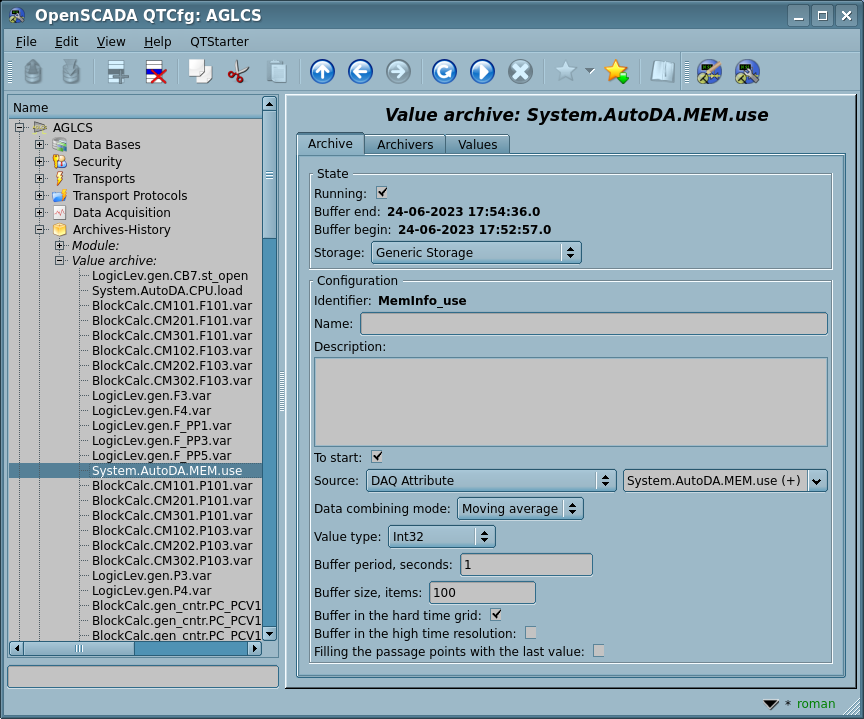
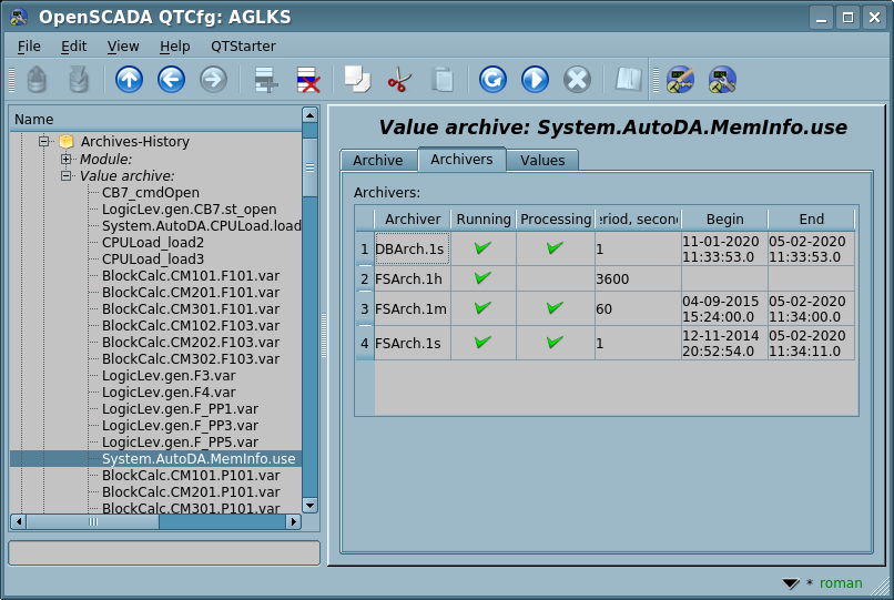
OpenSCADA values archives act as independent components that include buffers processed by archivers. The main parameter of the values archives is data source, in the role of which may be attributes of the parameters of the subsystem "DAQ", as well as other external data sources (passive mode). Other data sources may be network archivers of remote OpenSCADA stations, OpenSCADA programming environment, and more.
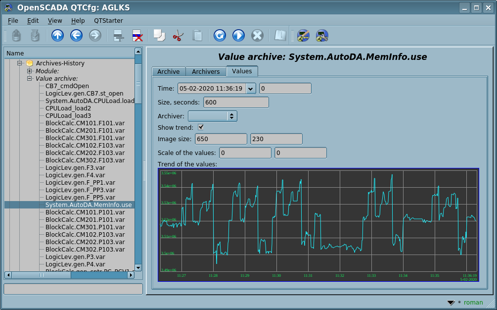
A key component of archiving the values of continuous processes is the value buffer, which is intended for intermediate storing of an array of values obtained with a defined periodicity (time quantum). The values buffer is used to directly store large values of arrays in the value archives both before the direct "flushing" on the physical storage, and for manipulating the value frames, that is, in the functions of the frame-by-frame query of the values and their location in the archive buffer.
To organize remote archivers in distributed configurations, the transport type of archivers is used, which is currently not implemented in OpenSCADA. The function of the transport type of archivers is to display the remote central archiver of OpenSCADA in the local configuration. As a result, the transport-type archiver performs data transfer between the local configuration and the archiver of the remote configuration of the program, by hiding from the subsystems of the local configuration the real nature of the archiver.
1.6 Communications, the subsystem "Transports" and "Transport protocols"
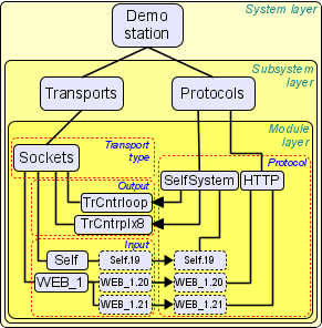
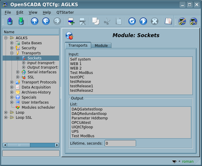
Since OpenSCADA is highly scalable, communication support should be sufficiently flexible, for which it is implemented in the "Transports" and "Transport protocols" subsystems (Fig.1.6), which are modular ones.
The "Transports" subsystem is intended to provide for the exchange of unstructured data between OpenSCADA and external systems, in the role of which remote stations OpenSCADA may also serve. Under unstructured data means the stream of characters of a certain length. Modular object contained in the "Transports" subsystem is a type of transport that determines the mechanism for the transmission of unstructured data. For example, their may be and are:
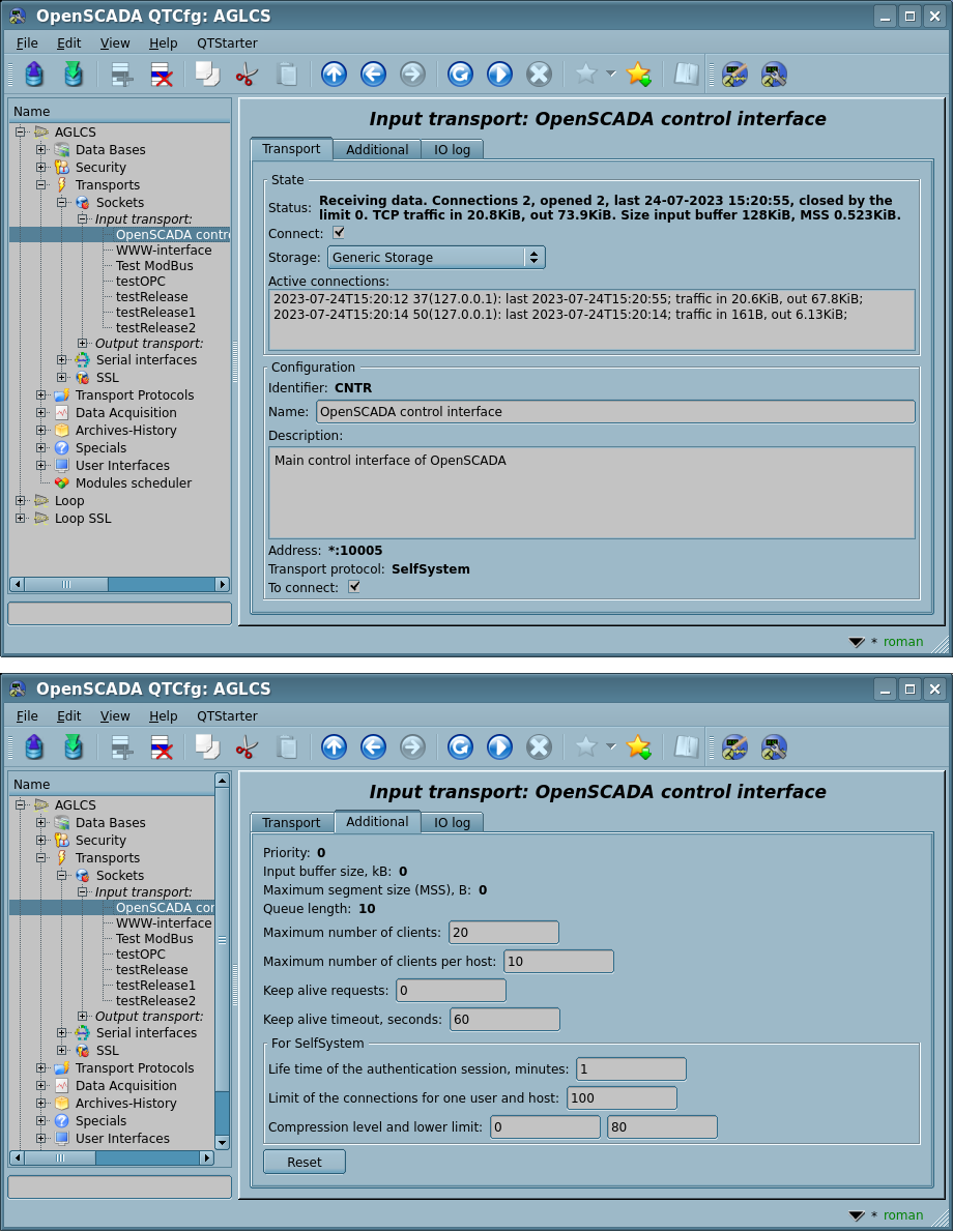
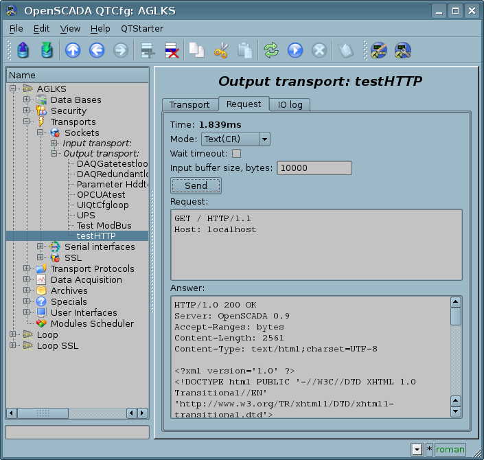
The subsystem "Transports" includes support for input and output transports. Input transports are designed to serve external requests and send replies. Output transports, by contrast, are designed to send messages and wait for a responses. Therefore, input transports contain configuration of local station, as a listening server, and output transports contain configuration of a remote server to connect. That sort of specialization is typical for the "request-response" mechanism, however, currently input and output transports support the independent transmission and reception of data. Modules of the subsystem "Transports" implement support for both input and output transports.
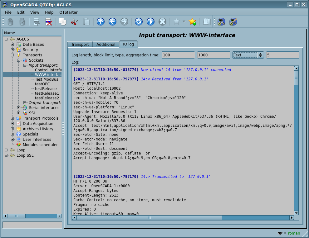
The "Transport protocols" subsystem is designed to structure data received from the "Transports" subsystem, why has the name, is a continuation of the subsystem "Transports" and performs functions of checking structure and integrity of received data. In global notation, this subsystem contains and implements COMMUNICATION protocols! A special configuration field is provided to determine protocol with which transport must operate. Modular object contained in the "Protocols" subsystem is protocol itself. For example, transport protocols can be and are:
- self OpenSCADA protocol;
- ModBus;
- OPC-UA;
- DCON;
- Hyper Text Transfer Protocol;
- user protocols, which are implemented into OpenSCADA itself on the logical level, and what, together of the internal language advancing, has become a priority one.
The full sequence of incoming communication session for typical "request-response" protocols can be written as follows:
- an external system connects to the input transport;
- a message from an external system comes to a transport;
- the transport transmits the message to a relating protocol by creating a new protocol object;
- the protocol checks the integrity of the data;
- if all the data came, then notify the transport about stopping of data waiting and send it an answer, otherwise tell that it should expect more;
- the transport, receiving confirmation, sends the answer and deletes the object of the protocol, if this is not the keep alive mode;
- if there is no confirmation, the transport continues to wait for the data, and in case of its receipt, it transmits to the saved object of the protocol.
Protocols are also supported for output transports and assume the function of communication with transport and implementation of features of these protocols, when preparing data for the transmission and analysis of responses. The external interface for accessing protocols, from code of other modules and the OpenSCADA programming environment, implements in an XML tree with its own structure for each protocol module. Such a mechanism allows for transparent access to external systems through transports, simply by specifying the name of the protocol by which to serve transmission.
Transports have a possibility to holding additional parameters, whose can be parameters of used protocols, that is protocols can be individually configured to each connection. [PLAN] In further this function will be used for the wrapping protocols.
Thanks to the standard access to transports in OpenSCADA, it's easy to change the way data is exchanged without affecting the exchanging programs themselves. For example, in the case of a local exchange, you can use faster transport based on UNIX-sockets and in the case of exchanging over the Internet and local network use TCP- or UDP-sockets.
1.7 User interfaces, the subsystem "User Interfaces"
SCADA systems, as a class, provide for user interfaces presence. In OpenSCADA for user interfaces, the subsystem "User Interfaces" is provided, which means not only the visualization environment that the end user must work with, but all that is relevant to the user, for example:
- Area of visualization: Visual Control Area engine, visualizators Qt and Web;
- Configurators: Qt and Web;
- Signaling.
The subsystem "User interfaces" is a modular one and its modular object is concrete that user interface itself. Modularity of the subsystem allows you to create different user interfaces in different GUI/TUI libraries and use the most optimal solution in a particular case, for example, you can use Web-based configurators and visualizers (WebCfg, WebCfgD, WebVision, WebUser), and in the case of stationary workstations, use the same configurators and visualizers, but on the basics libraries like Qt (QTCfg, Vision).
1.8 Security of the program, the subsystem "Security"
OpenSCADA is a ramified program that consists of a dozen subsystems and can include many modules. Therefore, giving everyone unlimited access to these resources is reckless, to say the least. In order to differentiate access, OpenSCADA provides the subsystem "Security" whose main functions are:
- storing user accounts and user groups;
- authentication of users;
- verifying access rights to a particular resource.
Besides this subsystem, the Control Interface also provides of the access checking per the control items and with logical dividing the permissions per subsystems for which there are automatically created the system groups, including this one — "Security". Currently any Control Node (TCntrNode) can have own access permition (ACL) which the Control Interface can use or save the compatibility before switching to it, and with saving the initial permissions on the subsystem root like to "root:DAQ"-0775.
Due to ACL is not obligatory or significant in many tasks, its specifying is integrated to point in the description fields of work nodes as a line of the ACL rule — "ACL: {owner}[:{group}[:{perm}]]", where:
- owner — owner of the resource;
- group — group of the resource;
- perm — permition of the resource whether in the symbol representing (RWXRWXRWX) or by the octal number (0777).
Currently ACL is supported by:
- the DAQ subsystem for Controller and Parameter Objects, DAQ-Templates, JavaLikeCalc Functions, most DAQ-Modules and by the OPC-UA module in the protocol part for checking permition of the authenticated user, where:
- Rd (04) — reading both the Control Nodes and the Parameter Attributes;
- Wr (02) — writing (also creating and removing) the Control Nodes;
- Xt (01) — execution-writing to the Parameter Attribute.
1.9 Management of modules, the subsystem "Modules scheduler"
OpenSCADA is built on the modular principle, which involves the presence of many modules that need to be controled and scheduled for availability, which is provided for the subsystem "Modules Scheduler". All modules are currently provided to the program through shared libraries (containers) or embedded directly into the OpenSCADA core library according to their logical connection. Each container can contain many different types of modules.
The subsystem "Modules scheduler" controls the state of the containers and allows "hot" plugging, deletion, and updating of the containers and modules it contains.
1.10 Unforeseen opportunities, the subsystem "Specials"
Obviously, it is impossible to predict all need functions and functions that may be needed in the future so OpenSCADA has the subsystem "Specials" that is modular and designed to provide unpredictable functions through modular extensions. For example, using this subsystem may be implemented:
- OpenSCADA and it modules' tests;
- libraries of user programming functions: system API functions, mathematics functions.
1.11 Functions, object model and programming environment of the user
Modern SCADA system should include mechanisms that enable programming at the user level, that is, the user programming environment. OpenSCADA contains this environment and can be used to:
- algorithms of control of technological processes;
- large dynamic real-time models and simulators of technological, chemical, physical and other processes;
- adaptive control mechanisms by models;
- user procedures for managing the internal functions of the program, its subsystems and modules;
- flexible formation of parameters of the subsystem "DAQ" in order to create parameters of a non-standard structure and fill them with the algorithm of the user; procedures and protocols for data acquisition on the user level;
- auxiliary calculations.
The programming environment is a set of tools that organize the user's computing area and includes
- object model;
- modules of libraries of functions;
- internal languages of the programming, currently — JavaLikeCalc, BlockCalc;
- dynamic calculations: objects of calculating controllers of the subsystem "DAQ", procedures and protocols of data acquisition of the user level, Widget procedures of "the Visual Control Area" and other.
Modules of function libraries provide static functions of a defined orientation, which extend the object model of the program and represent an user interface for accessing module resources. For example, "Visualization Control Area" can provide functions for issuing various messages, using which the user can implement interactive algorithms for interaction with the program. Function libraries can generally be implemented as a set of fixed-type functions — static ones, and functions that allow free modification and additions — dynamic ones.
Free-style function libraries (dynamic) provide the user-defined writing environment in one of the programming languages; at present, this language is similar to Java implemented by the module DAQ.JavaLikeCalc. In this way you can create libraries of devices of technological processes and many others, and then use them by binding.
On the basis of the functions given by the object model constructs objects of calculating controllers that carry out the binding of functions with the program parameters and the calculation mechanism. Also there construct procedures and protocols of data acquisition of the user level, Widget procedures of "the Visual Control Area" and much more.
2 SCADA systems and their structure
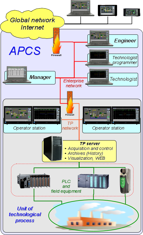
SCADA (Supervisory Control And Data Acquisition), in a general view, have the allocated architecture like represented on Figure 2. Elements of SCADA systems, in sense of the software, carry out following functions:
The acquisition server: represents a task or group of tasks engaged in data acquisition from sources of data, or act in a role as a source of data. Into tasks of the server enters:
- reception and-or formation of data;
- data processing;
- serving of requests about access to data;
- serving of requests about updating of data.
The server of archiving: represents a task or group of tasks engaged in archiving of data or their history maintenance. Into tasks of the server enters:
- archiving of data or their history maintenance of SCADA-systems;
- serving of requests for access to archival or history data;
- import/export of archives-history.
The logging server: represents a task or group of tasks engaged in archiving of messages or their history maintenance. Into tasks of the server enters:
- archiving of messages or their history maintenance of SCADA-systems;
- serving of requests about access to archival or history messages;
- import/export of archives-history.
The alarm server: represents a task or group of tasks carrying out functions of the server of logging concerning a narrow category of signaling-alarm messages.
The working place of operator: represents constantly functioning GUI (Grafical User Interface) application executed in an one-monitor, multimonitor or panel mode and carrying out functions:
- provision of an user interface for control over a condition of technological process;
- provision of an opportunity of formation of operating acts;
- provision of an opportunity of studying and analysis of history of technological process;
- provision of a toolkit for forming of reporting documentation.
The working place of engineer: represents GUI application used for configuration of SCADA systems. Into tasks of the application enters:
- provision of a toolkit for manipulation with system functions of the program;
- provision of a toolkit of a workplace of operator;
- provision of a toolkit for manipulation with distributed network architectures of SCADA systems as a whole (distribution of functions between stations, creation and removing of stations...).
The working place of chief: represents GUI application, executed in an one-monitor mode as a rule, and carrying out functions:
- provision of an user interface for control over a condition of technological processes;
- provision of a toolkit for studying and analysis of history of technological processes as directly from active servers, and on basis of separate archives;
- provision of a toolkit for forming of reporting documentations.
The working place of technologist: completely includes functions of workplace of operator plus models of technological processes (without direct communication with the technological processes).
The working place of technologist-programmer: completely includes functions of workplace of technologist plus a toolkit for creation of models of technological processes.
3 Ways of configuration and using
3.1 Simple server connection
In the elementary case OpenSCADA can be configured in a server mode (Fig.3.1) for acquisition and archiving of data. The given configuration allows to carry out following functions:
- interrogation of data sources (controllers);
- archiving of values of parameters of data sources;
- service of client requests about getting of various data of the server;
- granting of the configuration WEB-interface;
- the remote configuration from OpenSCADA by means of the Qt or other local interface.
- secondary regulation — regulation in objects of the computing controllers;
- simulating, correcting and appending calculations in objects of the computing controllers.
3.2 Duplicated server connection
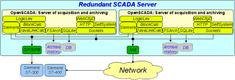
For increasing of reliability and productivity OpenSСADA supposes plural reservation (Fig.3.2) at which data sources (controllers) and archives-history of one copy are reflected in other. At use of a similar configuration there is possible distribution of loading of interrogation/calculation at various stations. The given configuration allows to carry out functions:
- interrogation of data sources (controllers);
- archiving of values of parameters of data sources;
- service of client requests about getting of various data of the server;
- reservation of parameters of the data sources;
- reservation of archives-history;
- distribution of loading of interrogation on servers;
- granting of the configuration WEB-interface;
- secondary regulation — regulation in objects of the computing controllers;
- simulating, correcting and appending calculations in objects of the computing controllers with an opportunity of distribution of loading on servers.
3.3 Duplicated server connection on one server
Special case of the duplicated connection is the duplicated connection within one server (Fig.3.3), that is starting of several stations at one machine with their parameters crossing. The purpose of the given configuration is increase of reliability and fault tolerance of the configuration by reservation of software.
3.4 Client access by means of the Web-interface. A place of the manager
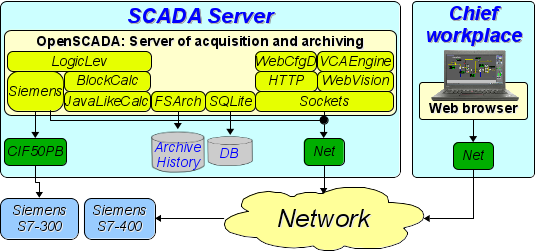
For visualization of data containing on a server, the good decision is to use the user WEB-interface (Fig.3.4). The given decision allows to use a standard WEB-browser at the client side and therefore is the most flexible as it is not related to one platform, i.e. is multiplatform. However this decision has essential imperfections — that is low productivity and reliability. In this connection it is recommended to use the given method for visualization of noncritical data or data having a reserve highly reliable way of visualization. For example, the good decision will be using of this method in the management of industrial plants where always exists an operator station with a reliable way of visualization. The given configuration allows to carry out following functions:
- interrogation of the server for acquisition of visualization data and configurations;
- visualization of data in a kind accessible to understanding;
- formation of protocols, reports;
- manipulation with parameters supposing change.
3.5 Automated workplace (place of the manager/operator)
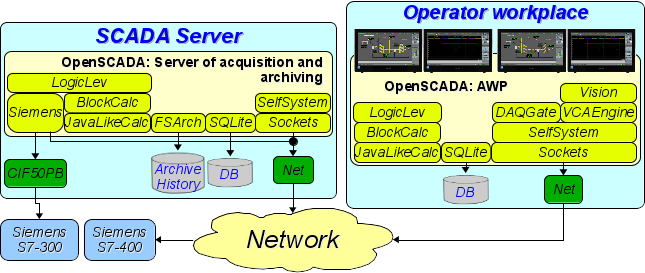
For visualization of critical data, and also in case of if high quality and productivity is required, it is possible to use visualization on the basis of OpenSCADA configured with a GUI module (Fig.3.5). The given configuration allows to carry out following functions:
- interrogation of the server for updating current values;
- visualization of the gathered data in a kind accessible to understanding;
- formation of protocols and reports;
- manipulation with parameters supposing changes.
3.6 AWP with a server of acquisition and archiving on single machine (place of the operator, simulator ...)
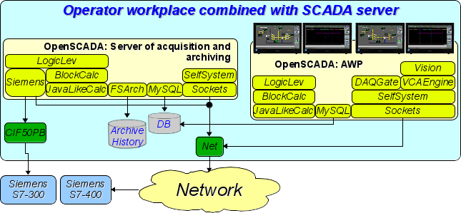
The full-function client-server configuration on single machine (Fig.3.6) can be used for increasing of reliability of the configuration as a whole by start of a client and a server in different processes. The given configuration allows, without consequences for the server, to stop the client and to do with it various preventive works. It is recommended for use at stations of the operator by installation of two machines combining in itself a station of the operator and a redundant server. The given configuration allows to carry out following functions:
- interrogation of data sources (controllers);
- service of client requests;
- visualization;
- performing of control actions;
- generation of protocols and reports;
- secondary regulation;
- simulating, correcting and appending calculations in objects of the computing controllers;
- acquisition and visualization of the information about the personal computer, the server....
3.7 Elementary mixed connection (simulator, demonstration, configurator ...)
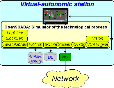
The mixed connection combines functions of a server and a client (Fig.3.7). It can be used for test, demonstration functions, and also for granting simulators of technological processes as a unit. In this mode following functions can be carried out:
- interrogation of controllers;
- service of client requests;
- visualization;
- delivery of operating influences;
- performing of control actions;
- secondary regulation;
- simulating, correcting and appending calculations in objects of the computing controllers;
- acquisition and visualization of the current information about the personal computer, the server, the simulator ...;
- configuration of databases, connections, etc.
3.8 Robust Distributed Configuration
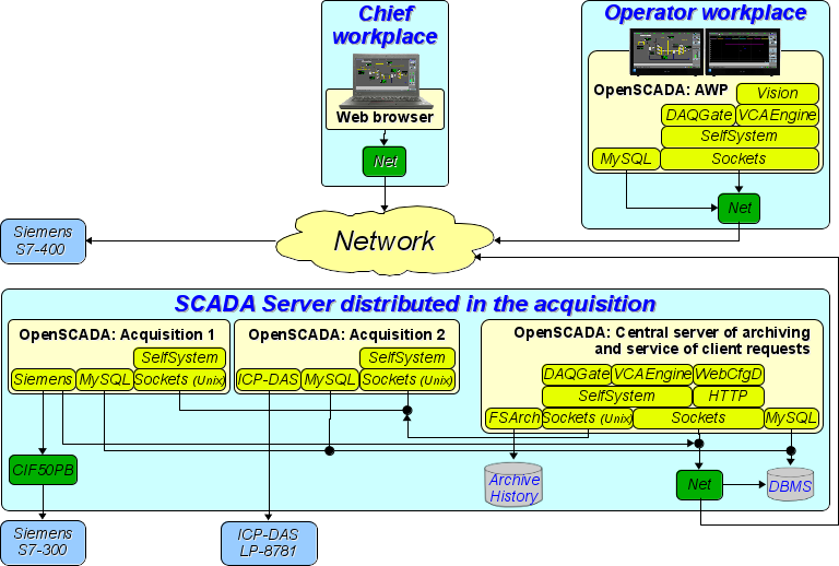
The given configuration is one of variants of robust/reliable connection (Fig.3.8). Stability is reached by distribution of functions on:
- to servers of acquisition;
- to the central server of archiving and service of client requests;
- to clients: AWPs and WEB-clients.
The acquisition server is configured on the basis of OpenSCADA and represents a task or a group of data collection tasks — acquisition of a controller or a group of controllers of the same type. Obtained values are available to the central server through any transport which support is added by connecting the corresponding transport module. To reduce the polling frequency and the value of network traffic, the polling server can be equipped with a small archive of values. Configuration of the acquisition server is stored in one of the available databases.
The central server of archiving and maintaining customer requests performs the centralized acquisition and processing of parameters of the polling servers and their values. Access to the polling servers is performed through one of transport + protocols available into OpenSCADA (for example, these Sockets). The module DAQGate is used to provide a single interface for accessing parameters and controllers, which reflects polling server data into the structure of local parameters of data acquisition.
To perform internal computations and additional analysis of parameters, objects of computing controllers are used.
Various archive-history modules are used for versatile and deep archiving.
For access of clients to the server are used accessible for OpenSCADA network transports, for example — Sockets, and transport protocols, for an example — the protocol OpenSCADA "SelfSystem".
The configuration of the central server is stored in one of accessible DB (for example it is network DBMS MySQL).
For granting the user WEB-interface the module WebCfgD by means of the transport protocol "HTTP" is used.
Various clients, including AWPs and WEB clients, are executed on separate machines in the right amount. AWP implements on OpenSCADA basis. Its function is to acquire the values of parameters from the central server and their visualization on the GUI interface(s). To obtain data acquisition parameters the DAQGate remote display parameters module is also used in the AWP. A network-type archive module can be used to provide access to archive-history. The AWP configuration can be stored in one of the available databases (for example, this is a network MySQL database located on the central archiving server machine).
4 Configuration and settings
As you can see in the section above, OpenSCADA provides possibility of configuration for execution in different roles. Support for this feature is provided by advanced configuration mechanisms, storage of configuration data and organization of projects of these configurations. This section contains a description of these mechanisms and is intended to give a presentment of flexibility and diversity, thus allowing OpenSCADA to be used for all 100 percent.
When describing the configuration mechanisms and storage methods in this section, emphasis will be placed on the common mechanisms. The specific of configuration and use of modules of OpenSCADA subsystems are provided in their own documentation of these modules.
OpenSCADA uses a declarative approach to describing the configuration interfaces based on the XML language. In fact, specifics of configuration of component of the program are provided by the component itself, thereby running through the entire program, as the nervous system of organism. In terms of OpenSCADA, this is called the OpenSCADA control interface (Control interface). Based on the control interface, graphical user configuring interfaces are created through the use of the OpenSCADA modules. This approach has the following important benefits:
- Scalability: you can only connect necessary configuration modules or only use remote mechanisms at all.
- Excluding of the need to update the configurators with the addition of new module functions, and exclusion of its "swelling" through the need of the direct support of the entire history of already unnecessary and obsolete functions-modules.
- Relative ease of creating graphical configuration interfaces on variety of the bases due to the clear formalization.
- Providing the possibility of dynamic configuration, that is, the configuration can be performed directly when the program is running both locally and remotely, directly controlling the result.
- Simple and targeted extensibility of configuration interface by adding configuration fields in the language of the description of the control interface only in components that need it.
To simplify the configuration process and storing its results, OpenSCADA provides projects of the program which self provide a separate OpenSCADA project folder to save there configuration and all related files. Thus, the OpenSCADA core employs the project selection mechanism, that install working folder and configuration file address according to the specified project. See "OpenSCADA projects" for more details.
OpenSCADA provides three configuration modules on different basis of visualization. Let's observe them and their configuration options:
- Configuration module on the GUI library Qt — UI.QTCfg. Provides an advanced configuration interface, allowing to operate as local stations and remote ones in local and global networks, including secure connection.
- Configuration module based on the dynamic WEB-technologies (DHTML) — UI.WebCfgD. Provides an advanced configuration interface, allowing to operate as local server's stations, and remote stations in local and global networks, including work on the secure connection. Client connection is provided through the usual Web-browser.
- Configuration module based on the static WEB-technologies (XHTML) — UI.WebCfg. Provides an adequate configuration interface that allows to manage local server's stations via the usual Web-browser.
The configuration can be received in three ways and in the following order: the command line of the program call, the Configuration File and the Data Base. Of which the Configuration File and Data Base are available for change, where the configuration values changed in the configurators are stored.
Typical name of the OpenSCADA configuration file is {sysconfdir}/oscada.xml (where sysconfdir typically is "/etc"), for configurations besides of the OpenSCADA projects, and {Proj}/oscada.xml for the project "Proj". Format of the configuration file and command line parameters we'll examine in the separate section.
Given the modularity of the subsystem "DB", the database may be different. Moreover, it is possible to store different parts of OpenSCADA both in different databases of the same type and in databases of different types.
Many OpenSCADA nodes provide the ability to select a storage to store their data and which can be specified as:
- Configuration File (<cfg>);
- {DB Module}.{DB Name} — Data Base;
- Generic Storage (<gen>) — the Generic Storage (combined) consisting of the Configuration File and the work Data Base specified in the "Work DB" configuration field; where the Configuration File is primary for the data already existing there, ie their changes, but everything new is created in the Data Base.
Nodes that do not provide the ability to select a storage work fixedly with the Generic Storage (<gen>), and those that do so also track the availability of their data in different storages and offer a mechanism for sequentially removing duplicates or simply detecting them in different libraries, which are formed by separate databases. You can read more about the mechanisms for transferring the configuration and extracting it to the library in the appropriate "How To".
Changing of some node's configuration will set the modification flag for the node, and also will set to active for buttons "Load from DB", for loading the initial configuration, and "Save to DB" for the changes saving. The modification flag also rises to parent node, which allows to restore-save from the root node, but really into the operations with DB will participate only modified nodes. ![]() A node removing causes to removing it from the storage and the modification mechanism does not work for this operation.
A node removing causes to removing it from the storage and the modification mechanism does not work for this operation.
Many settings and configurations of the OpenSCADA nodes, which are executed or already enabled, are not applied immediately at changes, because the configuration is read/apply usually only when turn on or start. Therefore to apply the changes, in such cases, it is enough to enable/disable the enabled object or to restart the running one — start/stop. At this time most settings those do not provide direct application are not allowed simply to be edited.
Further examining of configuration of OpenSCADA will be based on the interface of the configurator UI.QTCfg, but the principles of work will be fully consistent with the rest of the configurators owing to the generality in the used control interface of OpenSCADA.
Let's start the observing with configuration of the OpenSCADA system parameters that are placed in the six tabs of the root page of the station:
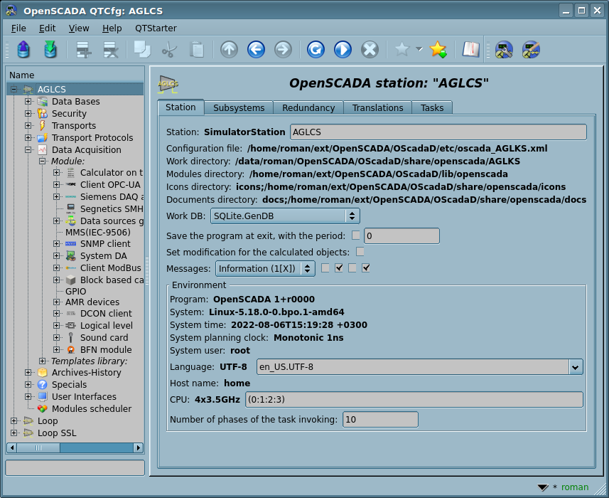
- The tab "Station" contains basic information and configuration fields of the station, Figure 4a. List the fields provided and comment on them:
- Station — contains information about the station's identifier and indicates the localized station's name. The identifier is specified by the command line parameter "--station"; when loading it is sought a section in the configuration file appropriate to the station identifier, and if not detected, it uses the first available one. The name is specified by the command line parameter "--statName".
- Configuration file — contains information about the configuration file used by the program. Set by the command-line parameter "--config" or the project.
- Work directory — contains information of the working directory of the station. This is used in relative addressing of objects in the file system, for example, database files. This is installed by the project manager at startup or directly in configuration the program launch.
- Modules directory — contains information of directories of modules of OpenSCADA, separated by ';', they can include a files' template in the end (/my/modules/path/lib*.so).
 If the value of this field is incorrect then when the program is started, the program ends with a message in the console that the configuration is incorrect.
 - Icons directory — contains information of directories of the program icons, separated by ';'.
 If the configuration navigation tree have no icons then the value of this field is incorrect.
 - Documents directory — contains information of directories of the program documents, separated by ';'.
 If you can not to call local documents then the value of this field is incorrect or the documentation is not installed.
 - Work DB — indicates the working Data Base, that is the Data Base part of the combined storage (Generic Storage) used to store main data of the program; which may be the Configuration File (<cfg>) also for excluding completely the Data Base from the data storage.
- Save the program at exit, with the period — points to the need to save the changed data at finishing of the program and indicates the periodicity in seconds with which to save the changed program's data.
- Set modification for the calculated objects — most suitable for the production systems together with the previous configuration properties, for the calculation context saving. But it is inconvinient in the development mode, all time reminding for the saving need.
- Messages — indicates the level of messages beginning from which they are to be processed and directions of the messages sending. Messages below this level will be ignored. The level "Debug (0)" have special sense, it set will enable debug messages generation by different parts of the program. To control the parts debug messages generation you can use the tab "Debug" (Fig.4d), which will be appeared in this case. The directions indicate the need of the message sending to the system logger, to the standard output, error and to the archive:
- the system logger is a mechanism of operation system for work with messages of the system and software; when this option is enabled the possibility appears to manage and control the OpenSCADA messages by the mechanisms of OS;
- the standard output and error direct the messages to console in the corresponded level; or to the standard log for some specific embedded systems;
- the archive of OpenSCADA messages is represented by the message buffer;
 this option is usually enabled and its disabling leads to the actual disabling of the archiving at the station; saving the message buffer to the storage is carried out by the appropriate message archiver whose creation and configuration can be found in detail in the configuration section of the subsystem "Archives-History".
- Environment — section of the environment information and configuration:
- Program — contains information of the program name and version. Usually it is OpenSCADA or name of a solution based on OpenSCADA.
- System — contains information of name and version of the Operational System (OS), OS kernel on which the program is executed.
- System time — contains information of the actual system time with the timezone.
- System planning clock — contains information of the used tasks planning clock and its resolution on the operation system. It allows you to orient with the minimum interval of time of periodic tasks, for example, for tasks of the data acquisition.
- System user — contains information of the user from whose the program is executed in OS.
- Language — contains information about the charset in which text messages are stored within the program and indicates the complete locale information with language, country and charset in the view "en_GB.UTF-8".
 Changing the complete locale here is acceptable and it is stored in the "Lang" field of the Configuration File, but it leads to change of messages' language for the interface and dynamic messages without restarting. For cleaning the "Lang" field you can just set here an empty value!
  In the MULTILANGUAGE-DYNAMIC mode language is taken not only from this field and the language is depended from the user execution context, which can overwrite this field to the context value according to the order:
- directly specified language (or locale) of the WEB-Browser or language-locale of the remote interface of the Qt-Modules;
- language of the used local user or "root";
- taken from non empty the "Lang" field of the Configuration File;
- value of the environment variable "LANG".
- Host name — contains information of the machine name that runs the station.
- CPU — contains the CPU operative information and indicates the main CPUs set for use by OpenSCADA tasks. The CPU information represents the accessible CPU/core number and the frequency, which runs the program. Value of frequency is checked every 10 seconds (for X86) and allows you to monitor its change by the power management mechanisms for example. The main CPUs set contains in round brackets a list of used currently CPUs.
- Number of phases of the task invoking — to set up phasing of the task invoking in the determined phases number, <= 0 to set optimal, 1 to disable the tasks phasing.
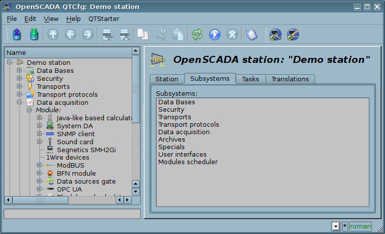
- The tab "Subsystems" contains the list of subsystems (Fig.4b) and allows you to jump directly to them using the context menu.
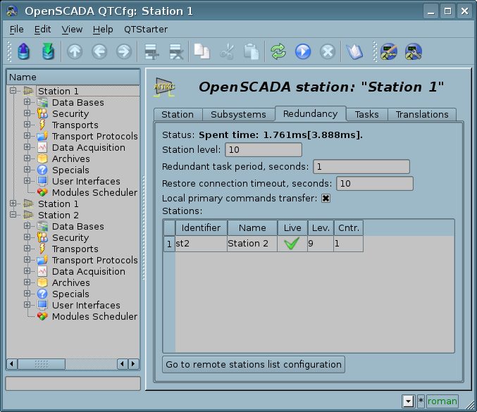
- The tab "Redundancy" (Fig.4c) contains the configuration of redundancy of the station with the following settings:
- Status — contains information on the redundancy mechanism, that is current and maximum time spent on the execution of one cycle of the task of redundancy processing.
- Station level — indicates the level of the station in a scheme of redundancy (0-255).
- Redundant task period, seconds — indicates the period of execution of the redundancy task in seconds (1-255).
- Restore connection timeout, seconds — indicates over the which period of time to attempt to reconnect with a lost redundant station in seconds (0-255).
- Local primary commands transfer — enables of local primary commands transfer to redundant stations for the local changes automatic sync.
- Stations — contains a table with information about the redundant stations. The stations can be added and removed via contextual menu. Id of the added stations is to be chosen from the list of available OpenSCADA stations. Presence into the table at last one enables the redundancy in whole and opens access to pages of the redundancy configuration at level of the subsystems, if a subsystem supports the redundancy. The table provides the following information about the station:
- Identifier — Identifier of the OpenSCADA station, should be changed after the addition by choosing from the list of available ones;
- Name — name of the OpenSCADA station;
- Live — sign of establishing of a connection with the redundant station;
- Level — level of the remote station in the redundancy scheme;
- Counter — requests' counter to the redundant station or waiting time, in the case of the absence of connection.
- Go to remote stations list configuration — command to go to the configuration page of the remote OpenSCADA stations in the subsystem "Transports".
- The tab "Translations" contains elements of the manager of central translation of text messages of the program (Fig.4f) and activates at the multi-language mode enabling by the base language of text variables set:
-
 You can learn more about the details and specifics of creating multilingual projects in the appropriate "How To".
- Status — current status of the project messages translation, where can be:
- "SINGLELANGUAGE, only use the already multilanguage DBs with their modification";
- "MULTILANGUAGE, creating or modification the configuration DBs as multilanguage ones with the pointed base language '{language}';
- "MULTILANGUAGE-DYNAMIC, and dynamic translation".
- Base language - locales list — enables the multilingual support for text variables in the configuration DBs by entry the base language and the project whole locales (like to "en_US.UTF-8") list (optional) separated by ';'. Further for the text variables in the non basic language in the tables of the database it will be created separate columns. Under the text variables the all text fields of configurator, which can be translated in another language, are meant. Numbers and other special symbols are not in their count and are not translated. The whole locales list is not an obligatory part and used mostly for conversion the language code to whole locale for system functions and in the locale selection lists.
-
 You can entry here other language besides English(en) as the base, but take in your mind that all standard OpenSCADA libraries formed for the base language English(en), so other base languages will break these DBs at change!
- , dynamic translation — planed state of the dynamic text messages translation. The dynamic text messages translation causes the text messages translation cache enabling and requests to the translations to the DB depends to the OpenSCADA part's language, mostly for multi-language dynamic user interfaces when user has self-preferred language and users of the program a lot, as a rule, are end-users-operators.
- Enable the manager — enables the generic translation manager which cause full reloading for all built messages obtain, however this does not form the full messages index by deny to reload some objects during their execution. For the full messages index loading you ought to save the manager into the enabled mode and to restart OpenSCADA. Ongoing next start the program will form the full messages index.
- Languages of managing — list of the processing languages separated by the character ';'. If the translations for the specified language in the source are presented then the language column will contain them otherwise it will be empty.
- Source filter — source filter of limiting the manager work in some DBs, the source just must contain such substring.
- , check/fix — enable for checking the base messages translation equality in different sources and fixing by: propagation the translations to empty sources, clearing the double to base translations. And the separated-second check for fixing by merging the base messages as the translations, since this operation can be some wrong in complex environments.
- , pass — pass the specified number of the table items from the top, useful for very big projects which are limited in time of the table complete processing.
- Messages — same the messages table with columns: the base language, managing translation languages, the message sources. To modify there are allowed the languages columns and at result the changes will be set to the message sources.
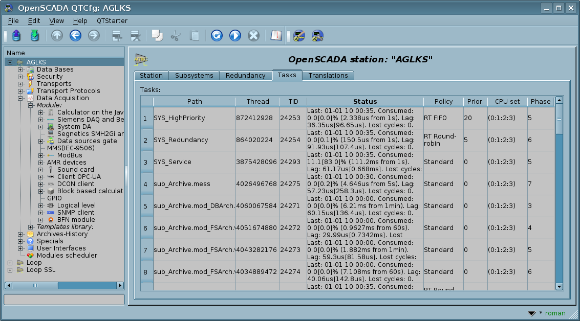
- The tab "Tasks" contains a table with opened tasks of OpenSCADA components (Fig.4d). From the table you can get several information about the tasks, and also assign CPUs used by the tasks of multiprocessing systems and set the task invoking phase.
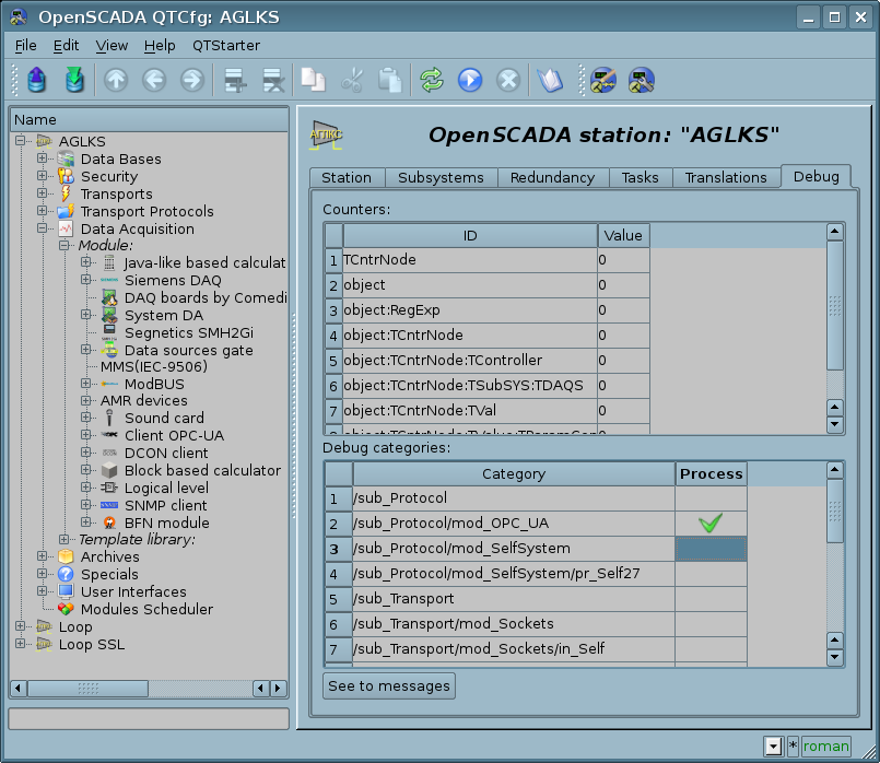
- The tab "Debug" contains elements for control to debug (Fig.4e) and activates at select the messages level "Debug (0)" or at the objects counters using.
To modify the fields of this page it may be required the super user's rights. Get these rights you can by means of including your user into the superuser's group "root", or by entering the station from the superuser "root".
We must mention another one important point: the fields of the identifiers of all OpenSCADA objects are unacceptable for direct editing, because they are keys for storage of objects' data inti the database. However, to change the object's identifier you can by the command of cutting and the further pasting of the object (Cut-> Paste) in the configurator.
Service task of the redundancy mechanism is always running and executed at intervals which are prescribed in the appropriate configuration field. Real work on implementing the redundancy is carried out in presence of at least one redundant station in the list of stations, and implies:
- Monitoring of connection with external stations. In the monitoring process the requests to remote stations are made to update information about them and to check the connection. In the case of loss of connection with a station the repeat of connection to it is made through interval specified in the configuration field "Restore connection timeout". In the "Live" field of the station the current state of communication is displayed. In the "Counter" field the number of requests carried to the remote station or the time remaining for the next connection attempt to the lost station is displayed.
- Local planning of the objects' execution in the redundancy. Planning is carried out in accordance with the station's level and preferences of execution of objects: controllers, messages archivators.
- Calling the data synchronization function for the local objects of the redundant subsystems working in the mode of synchronization of data from external stations.
It is recommended that the redundancy is configured in such a way that the database of the redundant stations are kept the same, which in the future will allow you to safely copy them, at restoration, to any station and, accordingly, you can save only one set of databases in the backup. In this case, the settings specific to the individual station will be stored in the configuration file and it will be possible to easily configure and change the desired station by choosing the appropriate configuration file.
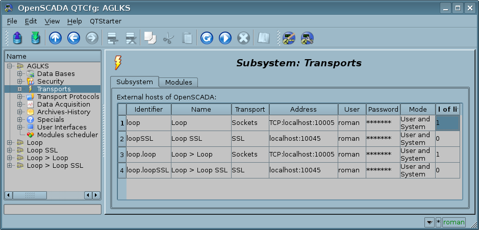
Redundancy configuration start from the redundant stations appending to the list of OpenSCADA stations in the tab "Subsystem" of the subsystem "Transports" (Fig.4.3b). And to add here you need not only the redundant stations to the current one but the same current one with its external IP, that is some loop. Further this configurations will have been stored into the generic DB of the redundant system, and from this time the DBs will be used in all redundant station creation. Then there is important to make on that stage all needed changes into the generic DB and about this project in general!
Next for the concrete station, with copy of the generic DB, we configure its specific parameters into the tab "Redundancy" of the main page (Fig.4c), which will be stored into the configuration file.
After that all next configurations of the redundancy perform into the tab "Redundancy" of proper subsystem — "Data acquisition" (Fig.4.5b) or "Archives" (Fig.4.6b). If you will set the parameter "Local primary commands transfer" (Fig.4c) then the configurations, like to any other generic ones, can be carried out at one of the stations, and the changes made will fall on all the redundant stations, of course, if they will be available.
For debug of specific of OpenSCADA different working you may be necessary to enable addition-debugging messages generation, which you can set by select minimal messages level, into the tab "Station", to "Debug (0)". As a result of this there will emerge the tab "Debug" (Fig.4e) where available the objects counters for control to leaks, and also the table with categories list of incoming debug messages. Into the table you can select only needed sources of the debug messages and omit to overload the archiving messages subsystem and to decrease significantly for overall performance of the program. You can also to select higher categories, up to root subsystems categories, that will disable the detailed selection and enable all messages generation by the level or by the overall subsystem. For the debug messages observing you need to go subsystem "Archives" (Fig.4.6c), and for this there provided the button "See to messages". The selected debug mode and list of debug categories can be standard stored to the configuration file and on the next boot the debug mode will be activated, this important primarily for the objects counters.
While examining configuration pages of the modular subsystems there will be described general properties of all the modules. However, it should be noted that each module can provide both additional tabs and separate fields for the configuration of its own operation features for pages whose objects are inherited by the modules. Information on the features and additions of the modules can be found in separate documentation for each of them.
4.1 Subsystem "DB"
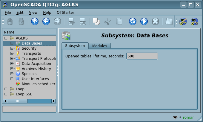
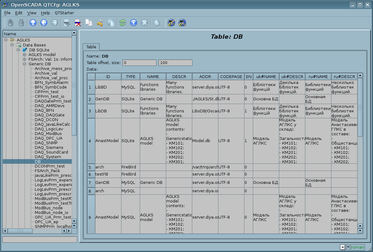
This subsystem is the modular one and contains a hierarchy of objects shown in Figure 1.4. To configure the subsystem the root page of the subsystem "DB" containing the tab "Subsystem" and the tab "Modules". The tab "Subsystem" (Fig.4.1a) contains currently only a configuration field for setting the opened tables lifetime, in seconds. The tab "Modules" (Fig.4.1b) is common for all subsystems and contains the list of modules in the subsystem "DB", available at the station.
To modify the page's fields of this subsystem it may be required the super user's rights or the inclusion of your user to the "DB" group.
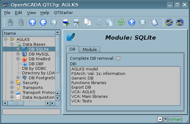
Each module of the subsystem "DB" provides a configuration page with tabs "DB" and "Module". The tab "DB" (Fig.4.1c) contains a list of database objects registered in the module and a sign of complete removal of database in execution of the deletion command. In the context menu of the database list, the user is given the opportunity to add, remove and switch to the desired database. The tab "Module" contains information about the module of the "DB" subsystem as the each module information fields (Fig.4.1d):
- Module — module identifier.
- Name — module name.
- Type — module type, identifier of the subsystem that contains the module.
- Source — shared library or *bd_{ModId}, for build-in , which characterizes the source of this module.
- Version — module version.
- Author — module author.
- Description — module short description.
- License — license agreement for distributing the module.
The "DB" subsystem modules contains also a specific information field "Features" with keyword list of supported features:
- LIST — tables-containers list in the DB-storage;
- GET, SEEK, SET, DEL — corresponded requests of OpenSCADA data records;
- STRUCT — obtain the DB fields structure in reflection to OpenSCADA data types;
- PRELOAD — preloading OpenSCADA data records at the SEEK-request, by the group SQL SELECT request;
- SQL — SQL-requests;
- FIX — fixing-changing the storage structure corresponding to the OpenSCADA data record structure;
- TR — processing the translation data of the OpenSCADA record structure;
- ERR — tested processing and logging of the environmental errors like to RO-mode, connection and so one.
For the OpenSCADA configuration storing, the storage implementation module must provide at least follow features: GET, SEEK, SET, DEL. And for being the multilanguage storage it must provide also the feature TR.
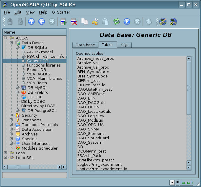
Each database object contains its own configuration page with the tabs "Data base", "Tables" and "SQL", in case support of SQL-requests. Besides the basic operations you can copy contents of DB by means of the standard function of the objects copying in the configurator. The copying operation of DB contents involves copying of an original database to a destination database, and the contents of the destination database is not cleared before the copy operation. Copying the contents of database is made only when the both databases are enabled, otherwise it will simple copy of the object of the database.
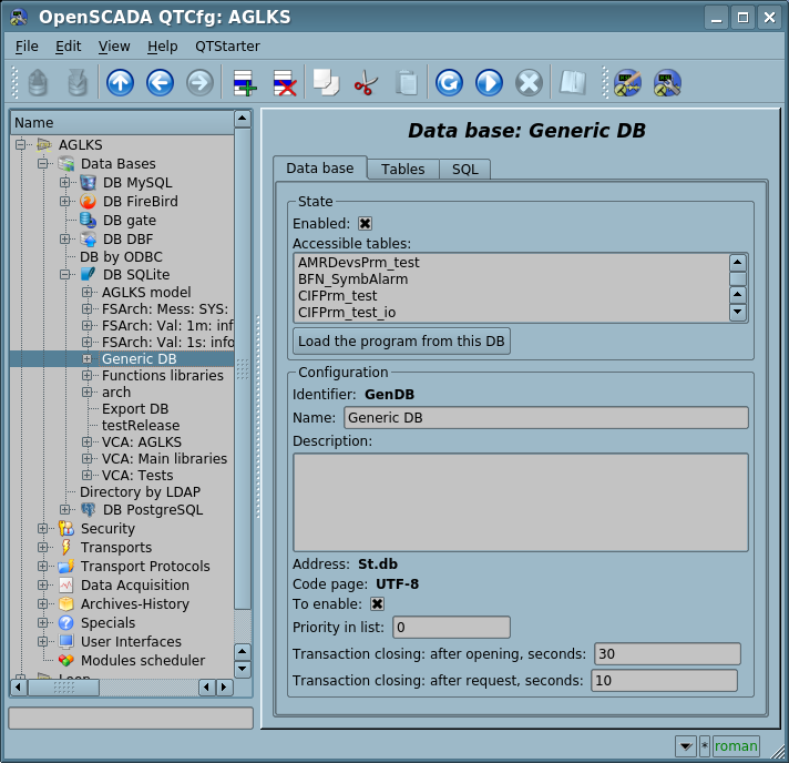
The tab "Data base" (Fig.4.1e) contains the main configuration options of the DB object as follows:
- Section "State" — contains the properties which characterise the DB object status:
- Enabled — state "Enabled" of the DB-object. For network databases this status involves connecting to the DBMS, respectively reflects the fact that there is a connection established and which, when set the sign "To enable", is periodically restored.
- Accessible tables — list of tables that are in the database. Context menu of the property gives the opportunity to physically remove the tables from the database.
- Load the program from this DB — command to make loading from this database. Can be used when transferring data in the database between stations. For example, you can to save a part of one station in an export database, to move physically the DB to another station and to connect it in this subsystem, and to call this command.
- Section "Configuration" — contains the following configuration fields:
- Identifier — contains directly the information on identifier of the DB object.
- Name — specifies the DB object name.
- Description — short description and appointment of the DB object and the DB itself.
- Address — DB address in specific format of the database type (module). Description of the recording format of the DB address is usually available in tooltip for this field.
- Code page — indicates a code page, in which text values of database are stored and provided. The value of the code page of database in conjunction with the internal code page of the station is used for clear transcoding of the text message while exchange between the station and the database.
- To enable — indicates the state "Enabled", in which to set the DB when start.
- Priority in list — the DB priority [0...99] in the common list of the databases used in the loading, useful for libraries placed in several databases for specifying the priority of the project — used ones.
- Transaction closing: after opening, seconds — time of closing the transaction after it opening.
- Transaction closing: after request, seconds — time of closing the transaction after the last request. If the time lesser than SERV_TASK_PER (10) then to process the DB transactions will be opened an independent thread-task with specified priority in the next option else the process will be performed by the service task.
- Transaction closing: separate task priority — priority of the independent thread-task, opened at the previous time lesser than SERV_TASK_PER (10).
The tab "Tables" (Fig.4.1f) contains a list of opened tables. In normal mode of the program operation this tab is empty, because after completion of working with tables the program closes them. Presence of opened tables tells that the program is now working with the tables or the tables are opened by the user to examine their contents. In context menu of the list of opened tables you can open a table for study (the command "Add"), close an opened table (the command "Delete") and proceed to examination of its contents.
The tab "SQL" (Fig.4.1g) allows only for data bases which support SQL-requests, and contains field to the request enter, button to the request send and table to result. Control of transaction mode of requests provided by a separate configuration field.
Page of examination of contents of tables contains only one the tab "Table". The tab "Table" (Fig.4.1h) contains a field of the name of the table and a table with the contents. The Table of contents provides following functions:
- redaction of content of cells of the table;
- addition of line;
- deleting of line.
4.2 Subsystem "Security"
This subsystem is not modular one. To configure the subsystem the root page of the subsystem "Security" is provided, which contains the tab "Users and Groups". This tab "Users and Groups" (Fig.4.2a) contains a list of users and users' groups. Users in the group "Security" or with the rights of the privileged user can add, delete the user or group of users. All other users can go to pages of users or groups of the users and change some personal parameters on the own user page.
For user configuration, a page that contains only the "User" tab (Fig.2.4b) is provided. This tab contains configuration data of the user profile, which can be changed by the user, the user in the "Security" group or the privileged user:
- Name — information about the name (identifier) of the user.
- Full name — specifies the full name of the user.
- Description — description and arbitrary information about the user.
- Password — the field to change the user's password. It always displays "********".
- Language — user's language for the dynamic messages context and for text to speech of the user interface. Empty to the system language.
- User picture — specifies the user's picture. Picture can be loaded and saved.
- Allow remote authentication — used by modules of remote accessing for allowing the user authentication.
- Groups — the table with a list of user groups and a sign of the user's belonging to the corresponding group.
- Storage — the user's data storage, with tracking the availability of the data in different storages and providing the sequentially removing duplicates.
To configure a group of users, a page is provided that contains only the "Group" tab (Fig.4.2c). This tab contains configuration data of the user group profile that can only be changed by the privileged user:
- Name — information about the name (identifier) of the user's group.
- Full name — specifies the full name of the user's group.
- Description — description and arbitrary information about the users group.
- Users — list of users included into this group. With the context menu of the list you can add or remove the user in the group.
- Storage — the user group data storage, with tracking the availability of the data in different storages and providing the sequentially removing duplicates.
4.3 Subsystem "Transports"
This subsystem is the modular one and contains the hierarchy of objects shown in Figure 1.6. To configure the subsystem it is provided the root page of the subsystem "Transports", containing the tabs "Subsystem" and "Modules".
The tab "Subsystem" (Fig.4.3a) contains a configuration table for external, for this, OpenSCADA stations. External stations may be "System", "User" or both these are selected by the appropriate column. System's external stations are available only to the super user and are used in purpose of components of the system, for example, the horizontal redundancy mechanism and the module DAQ.DAQGate. User's external stations are tied to the user who created them, and thus the list of user's external stations is individual for each user. User's external stations are used by components of the graphical interface, for example, UI.QTCfg, UI.WebCfgD and UI.Vision. In this table of external stations it is possible to add and delete records about the stations, as well as their modification. Each station contains the following fields:
- Identifier — identifier of the external station.
- Name — name of the external host.
- Transport — selection for the transport type or address directly from list of the network transports, output transports directly and input transports allowed to creation associated output connections.
- Address — additional address to the previous field used at creation the missed or automatic output transports and as the remote initiative connection ID for the input transports. Address of the external station through the output connection is specific to the module of the subsystem "Transports" selected in the previous field.
- User — name/identifier of the user of the external station on behalf of whom to perform the connection.
- Password — password of the user of the external station.
- Mode — host mode: "User", "System", "User and System".
- Uprising level — uprising hosts level of the pointed host for possibility of requests re-transmission.
The tab "Modules" (Fig.4.1b) contains a list of modules in the subsystem "Transports" and it is identical for all modular subsystems.
Each module of the subsystem "Transports" provides a configuration page with the tabs "Transports" and "Module".
The tab "Transports" (Fig.4.3b) contains a list of input and output transports registered by the module. Context menu of the transports lists provides the user with the possibility to add, delete and move to the desired transport. The output transports also provide a lifetime function of closing the transports at inactivity. Set it to 0 to disable this function!
On the "Module" tab it is provided the information about the module of subsystem "Transports" (Fig.4.1d), whose structure is identical for all modules.
Each transport contains its own generic configuration dialogues in the tab "Transport" and "Additional". The "Transport" tab contains basic transport settings. Input transport (Fig.4.3c) contains:
- Section "State" — contains the settings that characterize the state of the transport:
- Status — information on the current transport's status and statistics of its work. Most modules provide advanced diagnostics in this field when enabled with the debugging mode.
- Connect — operative state/command of the transport.
- Storage — the transport's data storage, with tracking the availability of the data in different storages and providing the sequentially removing duplicates.
- Active connections — active and actual connections list of the input transport.
- Section "Configuration" — directly contains the configuration fields:
- Identifier — information on the transport's identifier.
- Name — specifies the transport's name.
- Description — brief description of the transport and its appointment.
- Address — transport address in a specific type of transport (module) format. Description of the format of the address of the transport, as a rule, is available in the tooltip for this field.
- Transport protocol — indicates the transport protocol modules (the subsystem "Transport protocols") those should work in conjunction with the input transport. That is, received unstructured data this module will sent to the structuring and processing to the specified modules of the transport protocol.
- To connect — indicates the state/command "Connect", in which to transfer the transport at startup.
Output transport (Fig.4.3d) contains:
- Section "State" — contains the settings that characterize the state of the transport:
- Status — information on the current transport's status and statistics of its work. Most modules provide advanced diagnostics in this field when enabled with the debuging mode.
- Connect — operative state/command of the transport. Given the network nature of the transports, this state often involves connecting to a remote network node and accordingly reflecting the fact that the connection is present. For output transports, there is no need for the user to be obliged to set this state because it is used by an external entity of the communication protocols, often by the data sources, that try to connect the transport beforehand, so by establishing a connection for further exchange, moreover, the transport may be disconnected by that entity.
- Transport DB — the transport's data storage, with tracking the availability of the data in different storages and providing the sequentially removing duplicates.
- Section "Configuration" — directly contains the configuration fields:
- Identifier — information on the transport's identifier.
- Name — specifies the transport's name.
- Description — brief description of the transport and its appointment.
- Address — transport address in a specific type of transport (module) format. Description of the format of the address of the transport, as a rule, is available in the tooltip for this field.
The tab "Additional" of both input and output transports contains specific parameters of the transport type and protocols' specific custom parameters. Also there can be reset all the additional parameters to default values and be cleaned the protocols' specific custom parameters.
Output transport, in addition, provides a tab of forming user requests via this transport (Fig.4.3e). The tab is provided for debugging of communications and communication protocols, and includes:
- Time — information about the time spent on the request and the response.
- Mode — indicates the mode of data from the following list: "Binary", "Text(LF)", "Text(CR)", "Text(CR/LF)", in which the request will be formed and the answer will be provided. In the binary mode data is recorded in pairs of numbers in hex, i.e. bytes, separated by spaces.
- Wait timeout — sign of waiting timeout when received response. Many systems, when responding to different protocols (for example, HTTP), can send data responses in several pieces. Without this sign, only the first piece will be received and displayed. If the signs are set, all parts of the response will be expected, directly to the absence of data during the timeout waiting time of the transport.
- Input buffer size, bytes — controls the size of the input buffer or turns off the reading (0) at all — just reading.
- Send — command to send a request.
- Request — contains data of the request in the selected mode of the representing.
- Answer — provides data of the answer in the selected mode of the representing.
Both input and output transports also contain the tab "IO log" (Fig.4.3f). The tab is provided for generic control, observing and learning the traffic through the transports and includes the log length, block limit, type, aggregation time and the same text area of the log. For the log disable you can the log length field set to zero (0) and -1 for writing to a file. Writing to the file is performed for the files name "[in|out]_{TrModule}_{TrId}.log", with their rotation at specified size and count, and compression the rotated files.
4.4 Subsystem "Transport protocols"
This subsystem is the modular one. To configure the subsystem the root page of the subsystem "Transport Protocols" is provided, it contains the tab "Modules". The tab "Modules" (Fig.4.1b) contains a list of modules in the subsystem "Transport Protocols" and it is identical for all modular subsystems.
Each module of the subsystem "Transport Protocols" provides the configuration page with the tab "Module". On the tab "Module" there is information on the module of the subsystem "Transport Protocols" (Fig.4.1d), which structure is identical for all modules.
4.5 Subsystem "Data acquisition"
This subsystem is the modular one and contains the hierarchy of objects shown in Figure 1.3. To configure the subsystem the root page of the subsystem "Data acquisition" is provided, which contains the tabs: "Redundancy", "Template libraries" and "Modules".
To obtain access to modify the objects of this subsystem the user of the group "DAQ" or the rights of the privileged user are required.
As a redundancy object of the subsystem "Data Acquisition" there used the controller object for which the redundancy process performs that functions:
- Redundancy of the data acquisition mechanism. Typically, this function is realized without special mechanisms by simply running of the parallel redundancy stations with the same configuration and working independently. However, in the case at the station, which works as PLC, such approach is unacceptable because of the simultaneous making of control actions and the absence of synchronization of the calculators' data.
- Compensation of the data loss on the time of the node stop with the redundant node archive. There are two mechanisms of compensation. The first and the main mechanism implements the loading of the sections of the archive from the redundant station at the time of the station startup in general or of individual controller's objects as well as recovery after a long absence of communication. The section of the archive is requested from the moment of the last record in the local archive and till the current time. The depth of the request is limited by the definition of the limit time in the configuration of the redundancy. The second, complementary mechanism, performs the filling of the "holes" in the archive at the time of the actual user's request to the data. Such an approach on the one hand allows to make the predictable in time synchronization at startup and on the other hand it's actually eliminates the data loss in the case of working at least one station during the entire time.
- Load distribution of data acquisition between the nodes. When creating complex distributed systems there can be an important question of predicting and optimizing of the overall SCADA system performance. Taking into account these problems the redundancy mechanism provides the execution of tasks of data acquisition of individual sources (OpenSCADA controllers) only at one station. The other stations' tasks would go to the data synchronization mode with the executive station. In the case of loss of the connection with the executive station the task of the local data acquisition is started. It's also provided the possibility of optimal the load distribution of the execution of data acquisition task's of group of the controller objects between the stations.
- Optimization of the load on the external data sources through the data request from an external source by the only one node. In practice, we often meet highly loaded data sources or interfaces of access to the data sources, for which even the data acquisition by one station can be a problem and would require reducing the acquisition periodicity, i.e. data quality. The mechanism of redundancy, besides the load distribution between the stations as described above, allows you to remove an additional load form the data source and its interfaces, thereby improving the data quality. Writing to attributes of the controller's object under redundancy causes to the modification request sending to the master one, that is the writing through the master one.
- Prevention of some differences of data on different nodes associated with the mismatch of moments of time at the independent acquisition of data by individual nodes by means of receiving the data from the station with an active controller. In systems of high accountability under the redundancy there should be excluded or minimized the differences in the data at different stations, that means the real acquisition of data by one station and synchronization with these data of other ones.
The tab "Redundancy" (Fig.4.5a) presented only if at last one station (Fig.4c) pointed into the redundancy and contains the configuration of redundancy of data sources of the subsystem "Data acquisition" with the following settings:
- Depth time of restoring data at the starting — indicates the maximum depth of archival data to restore from the archive of the remote station when the starting in hours (0-12).
- Controllers — contains the table with the list of controller objects, available for redundancy, and their current status:
- Controller — full ID of the controller object;
- Name — name of the controller object;
- Running — sign of the controller object running on the local station;
- Redundancy — redundancy mode of the controller object, you can select it from the list:
- "Off" — absolutely independent work of the controller object.
- "Asymmetric" — full redundancy with the allowed controller object configuration of the remote station and without tries to generalize its.
- "Only alarms" — in fact it is work without redundancy but with oppressing of the alarms of the reserve controller object to exclude duple messages about the alarms.
- Preferable to run — configuration of the preferring execution at the specified station; the reserved values:
- <High Level> — running at the station with the highest level.
- <Low Level> — running at the station with the lowest level.
- <Optimal> — choice for the running of the least loaded station this is the station which runs lowest number of the controller objects.
- Remote — sign of indicating the running of the controller object on the remote station and work the local station in the mode of remote data synchronization.
The tab "Template libraries" (Fig.4.5b) contains a list of libraries of templates for the parameters of this subsystem. In the context menu of the list of template libraries the user can add, delete and move to the desired library. The tab "Modules" (Fig.4.1c) contains the list of modules in the subsystem "Transports" and it is identical for all modular subsystems.
Each template library of the subsystem "Data acquisition" provides a configuration page with the tabs "Library" and "Parameter templates". The tab "Library" (Fig.4.5d) contains the basic settings of the library:
- Section "State" — contains properties that characterize the state of the library:
- Accessing — state of library "Accessing".
- Storage — the library and templates data storage, with tracking the availability of the data in different storages and providing the sequentially removing duplicates.
-
 The object still supports of specifying the spare storage addresses with tables before you rename the table in the standard form "tmplib_{ObjID}".
- Date of modification — date and time for the object last modification.
- Section "Config" — directly contains the configuration fields:
- Identifier — information on the Id of the library.
- Name — specifies the name of the library.
- Description — short description of the library and its purpose.
The tab "Parameter templates" (Fig.4.5d) contains a list of templates in the library. In the context menu of the list the user can add, delete and go to the desired template.
Each template of the template library provides the configuration page with the tabs "Template" and "IO". The tab "Template" (Fig.4.5e) contains the basic settings of the template:
- Section "State" — contains properties that characterize the state of the template:
- Accessing — state "Accessing" of the template.
- Used — counter of the template's using. Allows you to determine whether the template is used and, consequently, the ability of structural changes of the template.
- Date of modification — date and time for the object last modification.
- Section "Configuration" — directly contains the configuration fields:
- Identifier — information on the identifier of the template.
- Name — specifies the name of the template.
- Description — short description of the template and its purpose.
The tab "IO" (Fig.4.5f) contains the configuration of attributes (Input-Output) of templates and the program text of the template on a language of the user programming of OpenSCADA, for example, "JavaLikeCalc.JavaScript". The sign "Translate program" indicates the preservation and translation of the program text for each language (human) separately, making it difficult to hold the algorithm the same for multilanguage configurations. This feature is generally implemented for compatibility with older versions of OpenSCADA, it is not recommended to install and is currently practicing the translation of specific text messages in the text of the program, through the function tr().
In the table of attributes of template user can, through the context menu: add, insert, delete, move up or down the record of attribute, as well as edit the attribute fields:
- Identifier — identifier of the attribute.
- Name — name of the attribute.
- Type — select the value's type of the attribute from the following: "Real", "Integer", "Boolean", "String", "String (translate)", "Text", "Text (translate)", "Object", "Integer numbers selection", "Real numbers selection", "Strings selection".
- Mode — select the mode from list: "Input", "Output". Typically used to indicate the direction of data transmission through links. I.e., values for the "Input" data link will only be obtained, and for the "Output" will also be transferred, in the case of modification.
- Attribute — mode of the parameter's attribute, implemented based on a template from the list: "No attribute", "Read Only", "Full access". For the attributes of a template, in which this field is set, it will be created an appropriate attribute in the controller's parameter of this subsystem.
- Configuration — configuration mode of an attribute in the configuration tab of a template of the controller's parameter of this subsystem from the list: "Variable", "Constant", "Link". In the "Constant" and "Link" modes in the configuration tab of a template will be added these attributes to set the constant or specify an external link of the parameter.
- Value — attribute's default value or link's template to access by the link:
- Format of the link's template depends on the component that uses it. Common links format is written in the following way "{Parameter}|{attribute}". The Parameter field — specifies the parameter's name as the attribute's container. Attributes with the equal value Parameter will be grouped and will be appointed only by the indication of the attributes' container, and the individual attributes will be associated with the attributes of the container in accordance with the field attribute.
- For selectable types the field may also contains of values list, in the second line, and names list, in the third line, with items separating by the symbol ";".
The syntax of the language of the template program can be found in the documentation of the module which provides the interpreter of the selected language. For example, a typical user programming language of OpenSCADA is JavaLikeCalc.JavaScript.
Each module of the subsystem "Data acquisition" provides the configuration page with the tabs "Controllers" and "Module". The tab "Controllers" (Fig.4.5g) contains the Number field with detailed quantity of the controller objects with the common statistic about ones: running, enabled and in errors per the error codes; also as a list of controller objects, registered in the module. In the context menu of the list user can add, delete and move to the desired controller object. On the tab "Module" there is information on the module of the subsystem "Data acquisition" (Fig.4.1d), which structure is identical for all modules.
Each controller object contains its own configuration page with the tabs "Controller", "Parameters" and "Diagnostics".
The tab "Controller" (Fig.4.5h) contains the basic settings. Content of these settings may differ slightly from one module of this subsystem to another, as you can find in the own documentation of the modules. As an example, let's examine the settings of a controller object in the module of the logical level controller DAQ.LogicLev:
- Section "State" — contains the properties, which characterize the state of the controller object and the controller itself:
- Status — specifies the controller object status. In our case, the controller is running and the current computation time is 1.15 milliseconds and the maximum one is 2.42 milliseconds.
- Enabled — state of the controller object "Enabled". When enabled, the controller object provides the possibility of creating the parameters and their configuration.
- Running — State of the controller object "Running". The running controller object performs the physical data acquisition and/or includes mechanisms for access to these data.
-
 Some data source types provides a possibility of performing some part of the function of coming to the Enabled state — hot updating the data configuration at the manual starting and that you can see in the field tooltip.
- Storage — data storage of the controller object and its parameters, with tracking the availability of the data in different storages and providing the sequentially removing duplicates. Parameters of different types are stored in different tables with own structure and unified name "{ModId}{TypeId}_{CntrId}", which can be specific for some modules.
- Date of modification — date and time for the object last modification.
- Section "Configuration" — directly contains the configuration fields:
- Identifier — information on the controller object identifier.
- Name — specifies the controller name.
- Description — brief description of the controller and its purpose.
- To enable — indicates the state of "Enabled", in which to transfer the controller object at the program startup.
- To start — indicates the state of "Running", in which to transfer the controller object at the program startup.
- Schedule of the calculation — defines whether periodic or scheduled character of the calculations is. In our example the template calculation is periodic in one second.
- Priority of the acquisition task — sets priority of the data acquisition of this controller. It is used when scheduling the operating system tasks. In the case of proper access availability this field enables the planning of the controller task in real time and with the specified priority otherwise it modifies the parameter "nice" of the task.
The tab "Parameters" (Fig.4.5i) contains a list of parameters in the controller object, provides selection of the type of parameters that are created by default, as well as information on the total number and the number of enabled parameters. In the context menu user can add, delete and go to the desired parameter.
The tab "Diagnostic" (Fig.4.5j) contains form of the diagnostic messages of the data source. Many data sources are external devices with accessing to the data by a network connection or a system bus then there possible different emergency situations on access to the data. Display all their to the field "State" of the controller object impossible due it displays only current access data state. Due the diagnostic you can trace all the emergency situations at view of messages, which forming by the controller object for the specified range of time and by the selected messages level. Besides to certain diagnostic information some modules of the data sources can provide here debug exchange dumps on the messages level "Debug (0)".
Parameters of the controller objects of the subsystem "Data acquisition" provide a configuration page with the tabs "Parameters", "Attributes", "Archiving", "Inclusion" and "Template configuration".
The tab "Parameter" (Fig.4.5k) contains the main settings:
- Section "State" — contains the properties, which characterize the state of the parameter:
- Type — specifies the parameter type. Type of disabled parameter can be changed if there are multiple types.
- Enabled — state of the parameter "Enabled". Enabled parameter is used by the controller for the data acquisition.
- Date of modification — date and time for the object last modification.
- Section "Configuration" — directly contains the configuration fields:
- Identifier — information on the parameter identifier.
- Name — specifies the parameter name.
- Description — brief description of the parameter and its purpose.
- To enable — indicates the state "Enabled" in which to transfer the parameter at the program startup.
- Parameter template — address of the previously discussed template.
The tab "Attributes" (Fig.4.5l) contains the parameter attributes and their values in accordance with the configuration of the used template and calculation of its program.
The tab "Archiving" (Fig.4.5m) contains a table with attributes of a parameter in the rows and the archivers in columns. The user can set the archiving for the desired attribute with the required archiver simply by changing the cell at the intersection.
The tab "Inclusion" (Fig.4.5n) contains a list of parameters included hierarchically to other parameter, provides information on the total number and the number of enabled parameters. In the context menu user can add, delete and go to the desired parameter. The parameters inclusion is supported by most the data sources and depth of the inclusion mostly limited 10 levels!
The tab "Template configuration" is't standard, but it is present only in the parameters of modules of the subsystem "Data acquisition", which implement the mechanisms of working under the template in the context of the data source, which they are served, for the logical type. In this review this tab is included for logical completeness of the review of parameter templates configuration of the subsystem "Data acquisition" and as the final stage of of their using. This tab (Fig.4.5o) contains the configuration fields in accordance with the template. In this example it is the group link on the external parameter. This link can be set simply by pointing the way to the parameter, if the flag "Show attributes" is not set, or the attribute addresses separately in the case if the flag is set. Sign "(+)" at the end of the address signals about successful linking and presence of the target.
4.6 Subsystem "Archives-History"
This subsystem is the modular one and contains the hierarchy of objects shown in Figure 1.5. To configure the subsystem the root page of the subsystem "Archives-History" is provided, which contains the tabs: "Redundancy", "Messages", "Values" and "Modules".
To gain the access to modify the objects of this subsystem the user of the group "Archive" or the privileged user rights are required.
As a redundancy object of the subsystem "Archives-History" there used the object of messages archiver for which the redundancy process performs followed functions:
- Redundancy of the archiving mechanism — means of the messages combination from the redundant stations by the three mechanisms:
- in the main cycle of the redundancy there performs a request for new messages of the archiver on the master station from the last message time of the redundant object, where the last message is the last second of the time what is requested twice to prevent of lose messages on this time second, but there is a mechanism for controlling duplicates and suppressing them both immediately after the request and by the archiver himself;
- writing and rewriting messages to the redundant archiver causes to redirection of the writing request to to the master station both for new and rewriting messages (also the messages write locally);
- rewriting messages to the master archiver causes to the messages sending for all redundant stations, where is excluded of creation new entries into the current violations table — only modification of presented ones.
- Compensation of the data loss on the time of the node stop with the redundant node archive. There provides only initial synchronisation by loading/reloading of parts of the archive from the redundant station, at the station starting in general. The archive's part requested from the moment of the last record into the local archive minus value of the parameter of the depth of the forced reloading and till the current time.
 Changed messages to more depth from the pointed will be lost on the started station! The initial synchronisation procedure involves in general:
- requesting for all active alarms;
- requesting for messages of concrete archive and on the depth specified by the parameter "Overtime of the reserve history reload at start" and up to the time of the previous request, so all new alarms won't definitely appear;
- coming to the normal mode of tracing new messages and alarms through the archive.
- Load distribution of the archiving between the nodes. When creating complex distributed systems there can be an important question of predicting and optimising of the overall system performance, taking this into the account the redundancy mechanism provides the execution of tasks of archiving of individual archivers only at one station. The other stations' tasks would go to the data synchronisation mode with the executive station. In the case of loss of the connection with the executive station the task of the local archiving is started. It's also provided the possibility of optimal the load distribution of the execution of archiving tasks of the archives group between the stations.
- Restoring of the alarms primacy. For the alarming messages, negative level, at their writing are performed an additional processing for the active alarms, that is only old-original ones are allowed for rewriting.
Redundancy of the values archiving doesn't provided directly but that process does through the data sources and the subsystem of "Data acquisition".
The tab "Redundancy" (Fig.4.6a) presented only if at last one station (Fig.4c) pointed into the redundancy and contains the configuration of redundancy of the messages archiving with the following settings:
- Overtime of the reserve history reload at start — points to the messages requesting depth, in days, at the redundant station from time of the last message into the local archive. Sometime that can be usable for reloading last messages if their can be potentially changed-updated on the redundant station at the time of the local one stopping.
- Message archivers — contains the table with the list of message archivers, available for redundancy, and their current status:
- Archiver — full identifier of the archiver;
- Name — name of the archiver;
- Running — sign of the archiver execution on the local station;
- Redundancy — redundancy mode of the archiver — enabling;
- Preferable to run — configuration of the preferring execution at the specified station; reserved values:
- <High Level> — running at the station with the highest level.
- <Low Level> — running at the station with the lowest level.
- <Optimal> — choice for the running of the least loaded station this is the station which runs lowest number of the archiver objects.
- Remote — sign indicating the running of the archiver on the remote station and work the local station in the mode of the remote data synchronization.
The tab "Messages" (Fig.4.6b) contains the configuration of the messages archive and the request form of messages from it.
Configuration of the messages archive is represented by the fields:
- Buffer size, archiving period — indicates the size of the memory area reserved for the interim buffer of messages. Messages from the buffer are requested for viewing and archived with the messages archivers by the specified periodicity in seconds.
- Days of the alarms automatic clearing — after that term the alarms are meant as forgotten and inactual, so removed from the table of the active alarms. Zero disables the automatic clearing.
The messages request form contains the configuration fields of the request and the table of results. Configuration fields of the request are:
- Time, depth and level — specifies the request time, depth and minimum level of messages (more or equal).
- Category pattern — specifies the category of the requested messages. In the category you can specify the elements of selection by template, that is the characters '*' — for any string and '?' — for any character, as well as a regular expression enclosed between the symbols '/' (/mod_(System|LogicLev)/).
- Archivers — indicates the messages archivers (separated by symbol ';'), for which the request is to be processed. If the value is missing, the request will be processed for the buffer and all archivers. If "<buffer>" is specified then the request will be processed for the messages buffer.
The result table contains rows of messages with the following columns:
- Time, mcsec — full date and time of the message and the microsecond part separately.
- Category — category o the message.
- Level — level of the message.
- Message — text of the message.
For alarm messages, after the table appears a button for clean up this table for the visible alarms, that is useful for service functions. The table also appended for the "Delete" command to remove single alarm.
The tab "Values" (Fig.4.6c) contains the general configuration of the values archiving and list of the value archives. In the context menu of the list of values the user has the opportunity to add, delete and go to the desired archive. The general configuration of the archiving is represented by the fields:
- Period of the data receiving — indicates the periodicity of the task of the active archiving, in milliseconds. Highest level of detail or minimum period of the active archives is in fact determined by this value.
- Level of priority of the data receiving task — sets priority of the task of the active archiving. It is used when scheduling the operating system tasks. In the case of proper access availability this field enables the planning of the archiving task in real time and with the specified priority otherwise it modifies the parameter "nice" of the task.
- Mode of forming ID of the automatic created archives — the mode of forming identifier at selecting the archiving in the tab "Archiving" of the DAQ-parameters.
- Number — detailed quantity of the value archives with the common statistic about ones: enabled, no source (passive), error (missing source), lost (empty storage), doubly linked.
- Value archives — list of the value archives itself.
- Remove all ... — group operations of removing all no source - passive, with error source - missing source, lost archives - empty storage, doubly linked.
The tab "Modules" (Fig.4.1b) contains the list of modules in the subsystem "Archives-History", available at the station.
The value archive of the subsystem "Archives-History" provides the configuration page with the tabs "Archive", "Archivers" and "Values".
The tab "Archive" (Fig.4.6d) contains the basic settings of the archive:
- Section "State" — contains the properties, which characterize the state of the archive:
- Running — state of the parameter "Running". Running archive collects data in the buffer and is served by the archivers.
- Begin and end of the buffer — date and time of values begin and end into the buffer.
- Storage — the archive's data storage, with tracking the availability of the data in different storages and providing the sequentially removing duplicates.
- Section "Configuration" — directly contains the configuration fields:
- Identifier — information on the archive identifier.
- Name — specifies the archive name.
- Description — brief description of the archive and its purpose.
- To start — indicates the state "Running" in which to transfer the archive at the program startup.
- Source — indicates the type and address of the source. Type of source is indicated from the list: "Passive", "DAQ Attribute" or "Active DAQ Attribute (DEPRECATED)". Passive archive does not have an associated source of values, the data to the such archive the source transfers by itself, for example from calculating procedures of users on internal programming language. Types with the attribute of the parameter in the address field indicate the parameter attribute of the subsystem "Data acquisition" as the source. Main attribute of the parameter sends data to the archive by itself with its own period of the data acquisition. Active attribute of the parameter is acquired by the archiving task of this subsystem. All real data sources work in the main archiving mode since the received data is immediately placed in the parameter attribute, sometimes by the source timestamp. The calculators (DAQ.JavaLikeCalc, DAQ.LogicLev, DAQ.BlockCalc, DAQ.Siemens, DAQ.OPC_UA) also works now in the main archiving mode and early used the active archiving mode because the data in the attribute parameter was updated only with them direct request, and was taken from the execution context. In the case of the real data sources, the difference between active and main mode of archiving by the fact that in the main mode the source can put data into the archive by timestamp, and in the active mode the timestamp is always set to the current system time.
- Data combining mode — sets the combining mode for data writing from the high-resolution buffer (for example, 1 second) to low-resolution archiver (for example, 1 minute), when into single point of the archiver placed several values (for example, 60) from the buffer. The modes implemented: "Moving average", "Single", "Minimum" and "Maximum".
- Value type — indicates the type of values which are stored in the archive from the list: "Boolean", "Integer", "Real", "String", "Int16", "Int32", "Int64", "Real(Float)" and "Real(Double)".
- Buffer period — indicates the periodicity of values in the archive buffer, in seconds.
- Buffer size — indicates the dimension or depth of the archive buffer. The dimension is automatically sets at a rate of 60 sec of the periodicity of the archiving task, with the remainder.
- Buffer in the hard time grid — indicates the mode of the buffer. The hard time grid mode involves the memory reservation for each value, but without the timestamp. This mode eliminates the possibility of packaging the adjacently-identical values but also saves on storage of the timestamp. Otherwise, the buffer operates in the mode of storage the value and timestamp and supports the packaging of adjacently-identical values.
- Buffer in the high time resolution — indicates the possibility of storing values at intervals and dimensions up to 1 microsecond, differently the values can be stored at intervals and dimensions up to 1 second.
- Filling the passage points with the last value — the passage values mostly fill by EVAL but sometime data periodicity of the source greater to the archive's one and it is normal.
Tab Archivers' (Fig.4.6e) contains the table with the configuration of the processing of the archive by the available archivers. Lines are available archivers, and the columns are the following parameters:
- Archiver — information on the archiver address.
- Running — information on the archiver state "Running".
- Processing — sign of the processing this archive be the archiver. The field is available for modification by the user.
- Period — information on the periodicity of the archiver, in seconds.
- Begin — date and time of beginning of the archive data in the archiver.
- End — date and time of ending of the archive data in the archiver.
The tab "Values" (Fig.4.6f) contains the values request in the archive and the result as a table of values or image of the trend. Values request contains the fields:
- Time — indicates the time of the request. It contains two fields: the field of date+time and microseconds.
- Depth — specifies depth of the request.
- Archiver — indicates values archiver for which the request is to be processed. If the value is empty, the request will be processed for the buffer and for all archivers. If "<buffer>" is specified then the request will be processed only for the archive buffer.
- Show trend — indicates the necessity for presentation of the archive data in the form of a graph (trend) otherwise the result is presented in a table that contains only time and value. In the case of toggle of this field the graph image is formed and displayed, additional configuration fields of the image settings are appeared:
- Image size — indicates the width and height of the generated image in pixels.
- Scale of the values — indicates the lower and upper border of the scale of the values. If both values are set to 0 or equal, then the scale will be determined automatically depending on the values.
Each module of the subsystem "Archives-History" provides configuration page with the tabs "Archivers" and "Module". The tab "Archivers" (Fig.4.6g) contains a list of archivers of messages and values registered in the module. The context menu of the list provides the user with possibility to add, delete and go to the desired archiver. On the tab "Module" there is information on the module of the subsystem "Archives-History" (Fig.4.1d), which structure is identical for all modules.
Message archivers contains their own configuration page with the tabs "Archiver" and "Messages".
The "Archiver" tab (Fig.4.6h) contains the basic settings. The structure of these settings may differ slightly from one module to another one of this subsystem as you can find in the own documentation of the modules. As an example we shall examine the settings of the message archiver from the module of the archiving on the file system Arch.FSArch Settings:
- Section "State" — contains the properties, which characterize the archiver state:
- Running — archiver state "Running". The running archiver processes the buffer of the message archive and puts his data in its repository, but also it processes requests for access to data in the repository.
- Storage — the archiver's data storage, with tracking the availability of the data in different storages and providing the sequentially removing duplicates.
- End and Begin of the archiver — date and time of the end and start of data in the archiver repository.
- Overall size of the archiver files — information about the total size of the archiver files with the data.
- Archiving time — current and maximum time spent on the archiving of data of the message archive.
- Section "Configuration" — directly contains the configuration fields:
- Identifier — information on the archiver identifier.
- Name — indicates the archiver name.
- Description — brief description of the archiver and its purpose.
- To start — indicates the state "Running" in which to transfer the archiver at the program startup.
- Message categories — list of categories of messages, separated by ';'. Messages matched with the templates or regular expressions of categories will be processed by the archiver. In the category you can specify the elements of selection by template, that is the characters '*' — for any string and '?' — for any character, as well as a regular expression enclosed between the symbols '/' (/mod_(System|LogicLev)/).
- Messages level — indicates the level of the archiver messages. Messages with the level greater than or equal to the specified one are processed by the archiver — taken from the buffer.
- Address — address of the storage in the specific for the type of archiver (module) format. The format description usually available in the tooltip for this field. In the example it is the relative path to the storage directory.
- Section "Additional options" — a specialized section for the module, the contents of which can be found in the documentation for the module.
The "Messages" tab (Fig.4.6i) contains the form of the messages request from the archive of the archiver:
- Time, depth and level — specifies the request date and time, depth and minimum level of messages (more or equal).
- Category pattern — indicates the category of the requested messages. In the category you can specify the elements of selection by template, that is the characters '*' — for any string and '?' — for any character, as well as a regular expression enclosed between the symbols '/' (/mod_(System|LogicLev)/).
The result table contains rows of messages with the following columns:
- Time, mcsec — full date and time of the message and the microsecond part separately.
- Category — category o the message.
- Level — level of the message.
- Message — text of the message.
Value archivers contains their own configuration page with the tabs "Archiver" and "Archives".
The "Archivator" tab (Fig.4.6j) contains the basic settings. The structure of these settings may differ slightly from one module to another one of this subsystem as you can find in the own documentation of the modules. As an example we shall examine the settings of the value archiver from the module of the archiving on the file system Arch.FSArch Settings:
- Section "State" — contains the properties, which characterize the archiver state:
- Running — archiver state "Running". The running archiver processes the buffers of the value archives and puts their data in its repository, but also it processes requests for access to data in the repository.
- Archiving time — current and maximum time spent on the archiving of data of the buffers of the archives. Periodicity of archiving is set in the field "Period of the archiving" in the section "Configuration" of the tab.
- Storage — the archiver's data storage, with tracking the availability of the data in different storages and providing the sequentially removing duplicates.
- Overall size of the archiver files — information about the total size of the archiver files with the data.
- Section "Configuration" — directly contains the configuration fields:
- Identifier — information on the archiver identifier.
- Name — indicates the archiver name.
- Description — brief description of the archiver and its purpose.
- To start — indicates the state "Running" in which to transfer the archiver at the program startup.
- Address — address of the storage in the specific for the type of archiver (module) format. The format description usually available in the tooltip for this field. In the example it is the relative path to the storage directory.
- Period of the values — indicates the periodicity of the values those are contained in the archiver repository, in seconds.
- Period of the archiving — indicates the periodicity of an archiving task of data of the buffers of the archives, in seconds. The size of the buffers of the archives in the time expression must not be less, and preferably somewhat greater, then the periodicity of the of archiving task. Set a zero period to disable the use of the archiver in processing the buffer — just a direct recording.
- Selection priority — selection of a priority of the archiver for using in the source mode "All". Set to zero for full the selection disabling.
- Section "Additional options" — a specialized section for the module, the contents of which can be found in the documentation for the module.
The "Archives" tab (Fig.4.6k) contains a table with information about the archives being processed by the archiver. The table in the rows contains the archives, and in the columns — the following information:
- Archive — archive name.
- Period, seconds — archive periodicity.
- Buffer size — buffer size, in units.
- Last read buffer — date and time of last reading of the buffer.
- Files size — specific to the module Arch.FSArch field with information about the total size of the files of the archiver storage for the archive.
In the case of the module Arch.FSArch in this tab you can find the form of exporting the archiver data.
4.7 Subsystem "User interfaces"
The subsystem is modular one. To configure the subsystem the root page of the subsystem "User Interfaces" is provided, it contains the tab "Subsystem" and the tab "Modules". The tab "Subsystem" (Fig.4.7a) contains currently only a configuration field for setting the syntax highlight font for code. The tab "Modules" (Fig.4.1b) contains a list of modules in the subsystem "User Interfaces" and it is identical for all modular subsystems.
Each module of the subsystem "User Interfaces" provides configuration page with the tabs "User Interface" and "Module". The "User Interface" tab (Fig.4.7b) provides the parameter for monitoring the "Running" status of the module, as well as the configuration sections specialized for the modules of this subsystem. On the "Module" tab it is provided the information about the module of subsystem "User Interfaces" (Fig.4.1d), whose structure is identical for all modules.
Due to the fact that most modules of this subsystem are graphical interfaces, they themselves can provide a developed configuration interface such as the UI.Vision module, and information on the specifics of their configuration can be find in their own documentation of these modules.
4.8 Subsystem "Specials"
The subsystem is modular one. To configure the subsystem the root page of the subsystem "Specials" is provided, it contains the tab "Modules". The tab "Modules" (Fig.4.1b) contains a list of modules in the subsystem "User Interfaces" and it is identical for all modular subsystems.
Each module of the subsystem "Specials" provides configuration page with the tabs "Special" and "Module". The "Special" tab (Fig.4.8) provides the parameter for monitoring the "Running" status of the module, as well as the configuration sections specialized for the modules of this subsystem. On the "Module" tab it is provided the information about the module of subsystem "Specials" (Fig.4.1d), whose structure is identical for all modules.
4.9 Subsystem "Modules scheduler"
The subsystem is not modular one. To configure the subsystem "Modules scheduler" the subsystem page is provided, it contains the tab "Subsystem". The "Subsystem" tab (Fig.4.9) contains the basic settings of the subsystem in the contains:
- Path to the shared libraries(modules) — information about the location of the directory with the modules of OpenSCADA. It is set by the parameter ModDir of the configuration file of the station.
- Denied modules — a list of the modules, separated by symbol ';', that are denied for automatically connection and updating. It is set by the parameter ModDeny of the subsystem section "sub_ModSched" of the configuration file of the station. The list of denied modules has higher priority than allowed ones.
- Allowed modules — a list of the modules, separated by symbol ',', that are allowed for automatic connection and renewal. The value '*' is used to allow all the modules. It is set by the parameter ModAllow of the subsystem section "sub_ModSched" of the configuration file of the station.
- Period of checking of the modules — indicates the period of checking the modules on the fact of their updating, in seconds. Modules those are allowed for automatically connection and updating will be automatically updated.
- Check the modules now — command to check the modules on the fact of their updating. Modules those are allowed for automatically connection and updating will be automatically updated.
- Shared libraries(modules) — a table with the list of shared libraries with the modules detected by OpenSCADA. Rows are modules and in the columns there is information about them:
- Source — the module(s) source, which is either the shared library or builtin code.
- Time — information about the date and time of the last modification of a shared library.
- Modules — information about the list of modules in a shared library.
- Enabled — state "Enabled" of the shared library. Privileged users are provided with an opportunity to manually enable/disable the shared libraries by changing this field.
4.10 Configuration File and command line parameters
The Configuration File of OpenSCADA is provided to store the generic configuration of OpenSCADA-station. Only in the Configuration File and through the command-line options you can specify a part of the key parameters of the station, so familiarity with the Configuration File structure is necessary for professionals who make peculiar solutions based on OpenSCADA. More information on how to startup and execution OpenSCADA can be found in the section "Startup and execution".
Structure of the Configuration File based on the extensible markup language XML. Correspondingly, strict compliance with XML syntax rules is required. An illustrative example of an OpenSCADA Configuration File with examples of the configuration of most OpenSCADA components is given...
<?xml version='1.0' encoding='UTF-8' ?>
<OpenSCADA>
<!--
This is the OpenSCADA configuration file.
-->
<station id="SimulatorStation">
<!--
Description of the internal parameters of the station.
The station is the OpenSCADA program.
-->
<prm id="StName">AGLKS</prm>
<prm id="WorkDB">SQLite.GenDB</prm>
<prm id="LogTarget">10</prm>
<prm id="LangBase">en_US.UTF-8;uk_UA.UTF-8;ru_RU.UTF-8</prm>
<prm id="SaveAtExit">0</prm>
<prm id="SavePeriod">0</prm>
<node id="sub_BD">
<tbl id="DB">
<fld ID="GenDB" TYPE="SQLite" NAME="Generic DB" NAME_uk="Основна БД" NAME_ru="Основная БД" ADDR="St.db" CODEPAGE="UTF-8" />
</tbl>
</node>
<node id="sub_Security">
<tbl id="Security_user">
<fld NAME="roman" DESCR="Roman Savochenko" PASS="$1$roman$wleNCf/uyA84cGpBn5QuG." />
<fld NAME="root" DESCR="Administrator (superuser)!!!" DESCR_uk="Супер користувач" DESCR_ru="Супер пользователь" PASS="$1$root$lCn57dP9yzkCIAyrwJ24r1" />
<fld NAME="test" DESCR="Test user" PASS="$1$test$pi/xDtU5WFVRqYS6BMU8X/" />
<fld NAME="user" DESCR="Simple user" DESCR_uk="Звичайний користувач" DESCR_ru="Простой пользователь" PASS="$1$user$k8sntSoh7jhsc6lwspjsU." />
</tbl>
<tbl id="Security_grp">
<fld NAME="Archive" DESCR="Archives-History" DESCR_uk="Архіви-Історія" DESCR_ru="Архивы-История" />
<fld NAME="BD" DESCR="Databases" DESCR_uk="Бази даних" DESCR_ru="Базы данных" />
<fld NAME="DAQ" DESCR="Data acquisition" DESCR_uk="Збір даних" DESCR_ru="Сбор данных" />
<fld NAME="ModSched" DESCR="Modules scheduler" DESCR_uk="Диспетчер модулів" DESCR_ru="Диспетчер модулей" />
<fld NAME="Protocol" DESCR="Transport protocols" DESCR_uk="Транспортні протоколи" DESCR_ru="Транспортные протоколы" />
<fld NAME="Security" DESCR="Security" DESCR_uk="Безпека" DESCR_ru="Безопасность" />
<fld NAME="Special" DESCR="Specials" DESCR_uk="Спеціальні" DESCR_ru="Специальные" />
<fld NAME="Transport" DESCR="Transports" DESCR_uk="Транспорти" DESCR_ru="Транспорты" />
<fld NAME="UI" DESCR="User Interfaces" DESCR_uk="Інтерфейси користувача" DESCR_ru="Интерфейсы пользователя" />
<fld NAME="root" DESCR="Administartors group" DESCR_uk="Група адміністраторів" DESCR_ru="Группа администраторов" USERS="roman;" />
<fld NAME="users" DESCR="Users group" DESCR_uk="Група користувачів" DESCR_ru="Группа пользователей" USERS="test;user;" />
<fld NAME="ITW" DESCR="IT worker" DESCR_uk="Робітник IT" DESCR_ru="Работник IT"
LONGDESCR="Information Technology or service worker."
LONGDESCR_uk="Робітник Інформаційних Технологій та сервісу."
LONGDESCR_ru="Работник Информационных Технологий и сервиса." />
<fld NAME="op" DESCR="Operator" DESCR_uk="Оператор" DESCR_ru="Оператор" />
</tbl>
</node>
<node id="sub_ModSched">
<prm id="ModAllow">*</prm>
<prm id="ModDeny" />
<prm id="ChkPer">0</prm>
</node>
<node id="sub_Transport">
<tbl id="ExtTansp">
<fld OP_USER="roman" ID="loop" NAME="Loop" NAME_uk="Петля" NAME_ru="Петля" TRANSP="Sockets" ADDR="TCP:localhost:10005" USER="roman" PASS="roman" />
<fld OP_USER="*" ID="loop" NAME="Loop" NAME_uk="Петля" NAME_ru="Петля" TRANSP="Sockets" ADDR="TCP:localhost:10005" USER="roman" PASS="roman" />
<fld OP_USER="roman" ID="loopSSL" NAME="Loop SSL" NAME_uk="Петля SSL" NAME_ru="Петля SSL" TRANSP="SSL" ADDR="localhost:10045" USER="roman" PASS="roman" />
<fld OP_USER="*" ID="loopSSL" NAME="Loop SSL" NAME_uk="Петля SSL" NAME_ru="Петля SSL" TRANSP="SSL" ADDR="localhost:10045" USER="roman" PASS="roman" />
</tbl>
<tbl id="Transport_in">
<fld ID="Self" MODULE="Sockets" NAME="Self system" DESCRIPT="Main transport of OpenSCADA self protocol."
DESCRIPT_uk="Основний транспорт власного протоколу OpenSCADA." DESCRIPT_ru="Основной транспорт собственного протокола OpenSCADA." ADDR="TCP::10005:1" PROT="SelfSystem" START="1">
<A_PRMS>&lt;prms MaxQueue="10" MaxClients="20" MaxClientsPerHost="5" BufLen="5" KeepAliveReqs="0" KeepAliveTm="60" /&gt;</A_PRMS>
</fld>
<fld ID="WEB_1" MODULE="Sockets" NAME="WEB 1" DESCRIPT="Main transport of the WEB interfaces."
DESCRIPT_uk="Основний транспорт WEB інтерфейсів." DESCRIPT_ru="Основной транспорт WEB интерфейсов." ADDR="TCP::10002:0" PROT="HTTP" START="1">
<A_PRMS>&lt;prms MaxQueue="10" MaxClients="100" MaxClientsPerHost="25" BufLen="5" KeepAliveReqs="0" KeepAliveTm="5" /&gt;</A_PRMS>
</fld>
<fld ID="WEB_2" MODULE="Sockets" NAME="WEB 2" DESCRIPT="Reserve transport of the WEB interfaces."
DESCRIPT_uk="Резервний транспорт WEB інтерфейсів." DESCRIPT_ru="Резервный транспорт WEB интерфейсов." ADDR="TCP::10004:0" PROT="HTTP" START="1">
<A_PRMS>&lt;prms MaxQueue="10" MaxClients="100" MaxClientsPerHost="25" BufLen="5" KeepAliveReqs="0" KeepAliveTm="5" /&gt;</A_PRMS>
</fld>
</tbl>
<!--
<tbl id="Transport_out">
<fld
ID="testModBus"
MODULE="Sockets"
NAME="Test ModBus"
NAME_uk="Тест ModBus"
NAME_ru="Тест ModBus"
DESCRIPT="ModBus protocol exchange test."
DESCRIPT_uk="Тест обміну за протоколом ModBus."
DESCRIPT_ru="Тест обмена по протоколу ModBus."
ADDR="TCP:localhost:10502"
START="1"/>
</tbl>-->
</node>
<node id="sub_DAQ">
<!--
<tbl id="tmplib">
<fld ID="test2" NAME="Test 2" NAME_uk="Тест 2" NAME_ru="Тест 2" DESCR="" DB="tmplib_test2"/>
</tbl>
<tbl id="tmplib_test2">
<fld ID="test2" NAME="Test 2" NAME_uk="Тест 2" NAME_ru="Тест 2" DESCR=""
PROGRAM="JavaLikeCalc.JavaScript&#010;cnt=5*i;"/>
</tbl>
<tbl id="tmplib_test2_io">
<fld TMPL_ID="test2" ID="i" NAME="I" NAME_uk="I" NAME_ru="I" TYPE="4" FLAGS="160" VALUE="" POS="0"/>
<fld TMPL_ID="test2" ID="cnt" NAME="Cnt" NAME_uk="Cnt" NAME_ru="Cnt" TYPE="4" FLAGS="32" VALUE="" POS="0"/>
</tbl>-->
<node id="mod_LogicLev">
<!--
<tbl id="DAQ">
<fld
ID="test2"
NAME="Test 2"
NAME_uk="Тест 2"
NAME_ru="Тест 2"
DESCR=""
ENABLE="1"
START="1"
PRM_BD="test2prm"
PERIOD="1000"
PRIOR="0"/>
</tbl>
<tbl id="test2prm">
<fld SHIFR="test2" NAME="Test 2" NAME_uk="Тест 2" NAME_ru="Тест 2" DESCR=""
EN="1" MODE="2" PRM="test2.test2"/>
</tbl>-->
</node>
<node id="mod_System">
<!--
<tbl id="DAQ">
<fld
ID="dataOS"
NAME="OS data"
NAME_uk="Дані ОС"
NAME_ru="Даные ОС"
DESCR="Data of services and subsystems of OS."
DESCR_uk="Дані сервісів та підсистем ОС."
DESCR_ru="Данные сервисов и подсистем ОС."
ENABLE="1"
START="1"
AUTO_FILL="0"
PRM_BD="DataOSprm"
PERIOD="1000"
PRIOR="0"/>
</tbl>
<tbl id="DataOSprm">
<fld SHIFR="CPU" NAME="CPU load" NAME_uk="Навантаження CPU" NAME_ru="Нагрузка CPU" DESCR=""
EN="1" TYPE="CPU" SUBT="gen"/>
<fld SHIFR="MEM" NAME="Memory" NAME_uk="Пам'ять" NAME_ru="Память" DESCR="" EN="1" TYPE="MEM"/>
</tbl>
-->
</node>
<node id="mod_DiamondBoards">
<!--
<tbl id="DAQ">
<fld ID="Athena" NAME="Athena board" NAME_uk="Плата Athena" NAME_ru="Плата Athena" DESCR=""
ENABLE="1" START="0" BOARD="25" PRM_BD_A="AthenaAnPrm" PRM_BD_D="AthenaDigPrm" ADDR="640" INT="5"
DIO_CFG="0" ADMODE="0" ADRANGE="0" ADPOLAR="0" ADGAIN="0" ADCONVRATE="1000"/>
</tbl>
<tbl id="AthenaAnPrm">
<fld SHIFR="ai0" NAME="AI 0" NAME_uk="AI 0" NAME_ru="AI 0" DESCR="" EN="0" TYPE="0" CNL="0" GAIN="0"/>
</tbl>
<tbl id="AthenaDigPrm">
<fld SHIFR="di0" NAME="DI 0" NAME_uk="DI 0" NAME_ru="DI 0" DESCR="" EN="0" TYPE="0" PORT="0" CNL="0"/>
</tbl>
-->
</node>
<node id="mod_BlockCalc">
<!--
<tbl id="DAQ">
<fld ID="Model" NAME="Model" NAME_uk="Модель" NAME_ru="Модель" DESCR=""
ENABLE="1" START="1" PRM_BD="Model_prm" BLOCK_SH="Model_blcks" PERIOD="1000" PRIOR="0" PER_DB="0" ITER="1"/>
</tbl>
<tbl id="Model_blcks">
<fld ID="Klap" NAME="Klapan" NAME_uk="Клапан" NAME_ru="Клапан" DESCR=""
FUNC="DAQ.JavaLikeCalc.lib_techApp.klap" EN="1" PROC="1"/>
</tbl>
<tbl id="Model_blcks_io">
<fld BLK_ID="Klap" ID="l_kl1" TLNK="0" LNK="" VAL="50"/>
<fld BLK_ID="Klap" ID="l_kl2" TLNK="0" LNK="" VAL="20"/>
</tbl>
<tbl id="Model_prm">
<fld SHIFR="l_kl" NAME="Klap level" NAME_uk="Положення клапану" NAME_ru="Положение клапана" DESCR=""
EN="1" IO="Klap.l_kl1"/>
</tbl>
-->
</node>
<node id="mod_JavaLikeCalc">
<!--
<tbl id="DAQ">
<fld ID="CalcTest" NAME="Calculation test" NAME_uk="Тест обчислення" NAME_ru="Тест вычисления" DESCR=""
ENABLE="1" START="1" PRM_BD="CalcTest_prm" FUNC="TemplFunc.d_alarm" SCHEDULE="1" PRIOR="0" ITER="1"/>
</tbl>
<tbl id="CalcTest_val">
<fld ID="in" VAL="0"/>
<fld ID="alrm" VAL=""/>
<fld ID="alrm_md" VAL="1"/>
<fld ID="alrm_mess" VAL="Error present."/>
</tbl>
<tbl id="CalcTest_prm">
<fld SHIFR="alrm" NAME="Alarm" NAME_uk="Аварія" NAME_ru="Авария" DESCR="" EN="1" FLD="alrm"/>
</tbl>
<tbl id="lib">
<fld ID="TemplFunc" NAME="" DESCR="" DB="lib_TemplFunc"/>
</tbl>
<tbl id="lib_TemplFunc">
<fld ID="d_alarm" NAME="Digit alarm" NAME_uk="Аварія за дискретним" NAME_ru="Авария по дискретному" DESCR=""
FORMULA="alrm=(in==alrm_md)?&quot;1:&quot;+alrm_mess:&quot;0&quot;;"/>
</tbl>
<tbl id="lib_TemplFunc_io">
<fld F_ID="d_alarm" ID="in" NAME="Input" NAME_uk="Вхід" NAME_ru="Вход" TYPE="3" MODE="0" DEF="" HIDE="0" POS="0"/>
<fld F_ID="d_alarm" ID="alrm" NAME="Alarm" NAME_uk="Аварія" NAME_ru="Авария" TYPE="0" MODE="1" DEF="" HIDE="0" POS="1"/>
<fld F_ID="d_alarm" ID="alrm_md" NAME="Alarm mode" NAME_uk="Режим аварії" NAME_ru="Режим аварии"
TYPE="3" MODE="0" DEF="" HIDE="0" POS="2"/>
<fld F_ID="d_alarm" ID="alrm_mess" NAME="Alarm message" NAME_uk="Повідомлення аварії" NAME_ru="Сообщение аварии"
TYPE="0" MODE="0" DEF="" HIDE="0" POS="3"/>
</tbl>-->
</node>
<node id="mod_Siemens">
<!--
<tbl id="DAQ">
<fld ID="test2" NAME="Test 2" NAME_uk="Тест 2" NAME_ru="Тест 2" DESCR="" ENABLE="1" START="1"
PRM_BD="test2prm" PERIOD="1000" PRIOR="0" CIF_DEV="0" ADDR="5" ASINC_WR="0"/>
</tbl>
<tbl id="test2prm">
<fld SHIFR="test2" NAME="Test 2" NAME_uk="Тест 2" NAME_ru="Тест 2" DESCR="" EN="1" TMPL="S7.ai_man"/>
</tbl>-->
</node>
<node id="mod_SNMP">
<!--
<tbl id="DAQ">
<fld ID="test2" NAME="Test 2" NAME_uk="Тест 2" NAME_ru="Тест 2" DESCR=""
ENABLE="1" START="1" PRM_BD="test2prm" PERIOD="1000" PRIOR="0" ADDR="localhost" COMM="public" PATTR_LIM="20"/>
</tbl>
<tbl id="test2prm">
<fld SHIFR="test2" NAME="Test 2" NAME_uk="Тест 2" NAME_ru="Тест 2" DESCR="" EN="1" OID_LS="system"/>
</tbl>-->
</node>
<node id="mod_ModBus">
<!--
<tbl id="DAQ">
<fld ID="test2" NAME="Test 2" NAME_uk="Тест 2" NAME_ru="Тест 2" DESCR="" ENABLE="1" START="1"
PRM_BD="test2prm" PERIOD="1000" PRIOR="0" TRANSP="Sockets" ADDR="exlar.diya.org" NODE="1"/>
</tbl>
<tbl id="test2prm">
<fld SHIFR="test2" NAME="Test 2" NAME_uk="Тест 2" NAME_ru="Тест 2" DESCR="" EN="1"
ATTR_LS="321:0:tst:Test"/>
</tbl>-->
</node>
<node id="mod_DAQGate">
<!--
<tbl id="DAQ">
<fld ID="test2" NAME="Test 2" NAME_uk="Тест 2" NAME_ru="Тест 2" DESCR="" ENABLE="1" START="1"
PRM_BD="test2prm" PERIOD="1000" PRIOR="0" SYNCPER="60" STATIONS="loop" CNTRPRM="System.AutoDA"/>
</tbl>-->
</node>
<node id="mod_DCON">
<!--<tbl id="DAQ">
<fld ID="test2" NAME="Test 2" NAME_uk="Тест 2" NAME_ru="Тест 2" DESCR="" ENABLE="1" START="1"
PRM_BD="test2prm" PERIOD="1" PRIOR="0" ADDR="" REQ_TRY="1"/>
</tbl>
<tbl id="test2prm">
<fld SHIFR="test2" NAME="Test 2" NAME_uk="Тест 2" NAME_ru="Тест 2" DESCR="" EN="1" MOD_TP="0"
MOD_ADDR="1" CRC_CTRL="1"/>
</tbl>-->
</node>
<node id="mod_ICP_DAS">
<!--<tbl id="DAQ">
<fld ID="test2" NAME="Test 2" NAME_uk="Тест 2" NAME_ru="Тест 2" DESCR="" ENABLE="1" START="1"
PRM_BD="test2prm" PERIOD="1" PRIOR="0" BUS="1" BAUD="115200" LP_PRMS="" REQ_TRY="3"/>
</tbl>
<tbl id="test2prm">
<fld SHIFR="test2" NAME="Test 2" NAME_uk="Тест 2" NAME_ru="Тест 2" DESCR="" EN="1"
MOD_TP="552985" MOD_ADDR="0" MOD_SLOT="1" MOD_PRMS="0"/>
</tbl>-->
</node>
<node id="mod_OPC_UA">
<!--<tbl id="DAQ">
<fld ID="test2" NAME="Test 2" NAME_uk="Тест 2" NAME_ru="Тест 2" DESCR="" ENABLE="1" START="1"
PRM_BD="test2prm" SCHEDULE="1" PRIOR="0" SYNCPER="60" ADDR="" EndPoint="opc.tcp://localhost:4841" SecPolicy="None"
SecMessMode="1" Cert="" PvKey="" AttrsLimit="100"/>
</tbl>
<tbl id="test2prm">
<fld SHIFR="test2" NAME="Test 2" NAME_uk="Тест 2" NAME_ru="Тест 2" DESCR="" EN="1" ND_LS=""/>
</tbl>-->
</node>
<node id="mod_SoundCard">
<!--<tbl id="DAQ">
<fld ID="test2" NAME="Test 2" NAME_uk="Тест 2" NAME_ru="Тест 2" DESCR="" ENABLE="1" START="1"
PRM_BD="test2prm" CARD="" SMPL_RATE="8000" SMPL_TYPE="1"/>
</tbl>
<tbl id="test2prm">
<fld SHIFR="test2" NAME="Test 2" NAME_uk="Тест 2" NAME_ru="Тест 2" DESCR="" EN="1" CHANNEL="0"/>
</tbl>-->
</node>
</node>
<node id="sub_Archive">
<prm id="MessBufSize">1000</prm>
<prm id="MessPeriod">5</prm>
<prm id="ValPeriod">1000</prm>
<prm id="ValPriority">10</prm>
<!--
<tbl id="Archive_mess_proc">
<fld
ID="StatErrors"
MODUL="FSArch"
NAME="Errors"
NAME_uk="Помилки"
NAME_ru="Ошибки"
DESCR="Archive of local errors"
DESCR_uk="Архів локальних помилок"
DESCR_ru="Архив локальных ощибок"
START="1"
CATEG="/DemoStation*"
LEVEL="4"
ADDR="ARCHIVES/MESS/stError/"/>
<fld
ID="NetRequsts"
MODUL="FSArch"
NAME="Network requests"
NAME_uk="Мережеві запити"
NAME_ru="Сетевые запросы"
DESCR="Requests to the server via Sockets transport."
DESCR_uk="Запити до сервера через транспорт Sockets."
DESCR_ru="Запросы к серверу через транспорт Sockets."
START="1"
CATEG="/DemoStation/Transport/Sockets*"
LEVEL="1"
ADDR="ARCHIVES/MESS/Net/"/>
</tbl>
<tbl id="Archive_val_proc">
<fld
ID="1h"
MODUL="FSArch"
NAME="1hour"
NAME_uk="1година"
NAME_ru="1час"
DESCR="Averaging at hour"
DESCR_uk="Усереднення за годину"
DESCR_ru="Усреднение за час"
START="1"
ADDR="ARCHIVES/VAL/1h/"
V_PER="360"
A_PER="60"/>
</tbl>
<tbl id="Archive_val">
<fld
ID="test1"
NAME="Test 1"
NAME_uk="Тест 1"
NAME_ru="Тест 1"
DESCR="Test 1"
DESCR_uk="Тест 1"
DESCR_ru="Тест 1"
START="1"
VTYPE="1"
BPER="1"
BSIZE="200"
BHGRD="1"
BHRES="0"
SrcMode="0"
Source=""
ArchS=""/>
</tbl>-->
</node>
<node id="sub_Protocol">
</node>
<node id="sub_UI">
<node id="mod_QTStarter">
<prm id="StartMod">QTCfg</prm>
<prm id="CloseToTray">0</prm>
<prm id="Style"></prm>
<prm id="Palette"></prm>
<prm id="StyleSheets"></prm>
<tbl id="LookFeel">
<fld NAME="Typical TDE" STYLE="" STL_SHTS="">
<PALETTE>#000000, #dddfe4, #ffffff, #ffffff, #555555, #c7c7c7, #000000, #ffffff, #000000, #ffffff, #efefef, #000000, #678db2, #ffffff, #0000ee, #52188b
#808080, #dddfe4, #ffffff, #ffffff, #555555, #c7c7c7, #c7c7c7, #ffffff, #808080, #ffffff, #efefef, #000000, #567594, #ffffff, #0000ee, #52188b
#000000, #dddfe4, #ffffff, #ffffff, #555555, #c7c7c7, #000000, #ffffff, #000000, #ffffff, #efefef, #000000, #678db2, #ffffff, #0000ee, #52188b</PALETTE>
</fld>
<fld NAME="Blue Slate" STYLE="" STL_SHTS="">
<PALETTE>#000000, #9db9c8, #f6fcff, #c9dae3, #4e5c64, #697b85, #000000, #bfe2f4, #000000, #c3c3c3, #9db9c8, #000000, #558097, #ffffff, #0000ee, #52188b, #b4b4b4, #000000, #ffffdc, #000000
#808080, #9db9c8, #f6fcff, #b5d5e6, #4e5c64, #697b85, #808080, #bfe2f4, #808080, #c3c3c3, #9db9c8, #000000, #558097, #808080, #0000ee, #52188b, #b4b4b4, #000000, #ffffdc, #000000
#000000, #9db9c8, #f6fcff, #b5d5e6, #4e5c64, #697b85, #000000, #bfe2f4, #000000, #c3c3c3, #9db9c8, #000000, #558097, #ffffff, #0000ee, #52188b, #b4b4b4, #000000, #ffffdc, #000000</PALETTE>
</fld>
<fld NAME="Blue Darkness" STYLE="" STL_SHTS="">
<PALETTE>#ffffff, #426794, #5788c3, #4871a2, #162231, #37567b, #dcdcdc, #5788c3, #ffffff, #002a4e, #426794, #000000, #5cb3ff, #000000, #00ffff, #c0c0ff
#555555, #426794, #5788c3, #4871a2, #162231, #37567b, #37567b, #5788c3, #555555, #002a4e, #426794, #000000, #4c95d4, #ffffff, #00ffff, #c0c0ff
#ffffff, #426794, #5788c3, #4871a2, #162231, #37567b, #dcdcdc, #5788c3, #ffffff, #002a4e, #426794, #000000, #5cb3ff, #000000, #00ffff, #c0c0ff</PALETTE>
</fld>
</tbl>
</node>
<node id="mod_QTCfg">
<prm id="StartUser">roman</prm>
</node>
<node id="mod_Vision">
<prm id="StartUser">roman</prm>
</node>
<node id="mod_WebCfg">
<prm id="SessTimeLife">20</prm>
</node>
<node id="mod_VCAEngine">
<!--
<tbl id="LIB">
<fld ID="test2" NAME="Test 2" NAME_uk="Тест 2" NAME_ru="Тест 2" DESCR=""
DB_TBL="wlib_test2" ICO="" USER="root" GRP="UI" PERMIT="436"/>
</tbl>
<tbl id="wlib_test2">
<fld ID="test2" ICO="" PARENT="/wlb_originals/wdg_Box" PROC="" PROC_PER="-1"
USER="root" GRP="UI" PERMIT="436"/>
</tbl>
<tbl id="wlib_test2_io">
<fld IDW="test2" ID="name" IO_VAL="Test 2" IO_VAL_uk="Тест 2" IO_VAL_ru="Тест 2" SELF_FLG="" CFG_TMPL="" CFG_VAL=""/>
<fld IDW="test2" ID="dscr" IO_VAL="Test of the module 2" IO_VAL_uk="Тест модуля 2" IO_VAL_ru="Тест модуля 2" SELF_FLG="" CFG_TMPL="" CFG_VAL=""/>
</tbl>
<tbl id="PRJ">
<fld ID="test2" NAME="Test 2" NAME_uk="Тест 2" NAME_ru="Тест 2" DESCR="" DB_TBL="prj_test2" ICO="" USER="root" GRP="UI" PERMIT="436"/>
</tbl>
<tbl id="prj_test2">
<fld OWNER="/test2" ID="pg1" ICO="" PARENT="/wlb_originals/wdg_Box" PROC="" PROC_PER="-1" USER="root" GRP="UI" PERMIT="436" FLGS="1"/>
<fld OWNER="/test2/pg1" ID="pg2" ICO="" PARENT="/wlb_originals/wdg_Box" PROC="" PROC_PER="-1" USER="root" GRP="UI" PERMIT="436" FLGS="0"/>
</tbl>
<tbl id="prj_test2_incl">
<fld IDW="/prj_test2/pg_pg1" ID="wdg1" PARENT="/wlb_originals/wdg_Box"/>
</tbl>-->
</node>
</node>
<node id="sub_Special">
<node id="mod_SystemTests">
<prm id="Param" on="0" per="5" name="LogicLev.experiment.F3" />
<prm id="XML" on="0" per="10" file="/etc/oscada.xml" />
<prm id="Mess" on="0" per="10" arhtor="DBArch.test3" depth="10" />
<prm id="SOAttach" on="0" per="20" name="../../lib/openscada/daq_LogicLev.so" mode="0" full="1" />
<prm id="Val" on="0" per="1" name="LogicLev.experiment.F3.var" arch_len="5" arch_per="1000000" />
<prm id="Val" on="0" per="1" name="System.AutoDA.CPULoad.load" arch_len="10" arch_per="1000000" />
<prm id="DB" on="0" per="10" type="MySQL" addr="server.diya.org;roman;123456;oscadaTest" table="test" size="1000" />
<prm id="DB" on="0" per="10" type="DBF" addr="./DATA/DBF" table="test.dbf" size="1000" />
<prm id="DB" on="0" per="10" type="SQLite" addr="./DATA/test.db" table="test" size="1000" />
<prm id="DB" on="0" per="10" type="FireBird" addr="server.diya.org:/var/tmp/test.fdb;roman;123456" table="test" size="1000" />
<prm id="TrOut" on="0" per="1" addr="TCP:127.0.0.1:10001" type="Sockets" req="time" />
<prm id="TrOut" on="0" per="1" addr="UDP:127.0.0.1:10001" type="Sockets" req="time" />
<prm id="TrOut" on="0" per="1" addr="UNIX:./oscada" type="Sockets" req="time" />
<prm id="TrOut" on="0" per="1" addr="UDP:127.0.0.1:daytime" type="Sockets" req="time" />
<prm id="SysContrLang" on="0" per="10" path="/Archive/FSArch/mess_StatErrors/%2fprm%2fst" />
<prm id="ValBuf" on="0" per="5" />
<prm id="Archive" on="0" per="30" arch="test1" period="1000000" />
<prm id="Base64Code" on="0" per="10" />
</node>
</node>
</station>
</OpenSCADA>
Let's examine the structure of the configuration file in detail. One configuration file can contain the configuration of several stations in the sections <station id="SimulatorStation"/>. The "id" attribute specifies the station identifier — class of the station. Use of this or that section of the station is indicated by the command line parameter --station=SimulatorStation when starting. The section of the station directly contains station parameters and subsystem sections. Section configuration parameters are written as <prm id="StName">AGLKS</prm> , where the "id" attribute specifies the parameter ID, and in the body of the "prm" tag, the value "AGLKS" for the parameter is specified. The list of available parameters and their description for the station and all other sections can be obtained from the console by starting OpenSCADA with the parameter --help.
The subsystem sections <node id="sub_DAQ" /> contain: subsystem parameters, module sections, and table sections for reflections of the data of databases in the configuration file. Module sections <node id="mod_DiamondBoards" /> contain individual module parameters and table sections for reflections of the data of databases in the configuration file.
Default values of the command-line options and generic parameters you can pass through environment variables in form "OSCADA_{OPT}={VAL}" after enabling by the environment variable OSCADA_CMD_EN, like to — OSCADA_CMD_EN=1 OSCADA_log=0 OSCADA_limObjDscr_SZ=1000 OSCADA_sub_UI_mod_QTStarter_Style=Fusion ./openscada_AGLKS. That is you can prepare individual default environment of OpenSCADA execution for your system in whole in a file of the folder /etc/profile.d/ or for concrete user in the file {USER-HOME}/.profile.
The sections of the tables of reflection of the data of databases are provided for placement in the configuration file records of DB tables for the OpenSCADA components. Let's examine the table of the input transports "Transport_in" of the subsystem "Transports" <node id="sub_Transport"> from the above provided example of the configuration file. The table contains three records with the fields: ID, MODULE, NAME, DESCRIPT, ADDR, PROT, START. After starting with this section and in general without the DB in the subsystem "Transports" of the module "Sockets" you'll see three input transports. The formats of the table structures of the main components are included into the demo configuration file — models of technological processes. For details of the structure of the database tables refer to the documentation of the corresponding modules or simply save the desired object to the configuration file.
The result of the command execution openscada_AGLKS --help ...
***************************************************************************
********** OpenSCADA v0.9+r2535 (Linux-4.9.0-0.bpo.5-amd64). *********
***************************************************************************

===========================================================================
==================== Generic options ======================================
===========================================================================
-h, --help              This help text about the program command-line options and configuration file parameters.
    --projName=<name>   OpenSCADA project name to switch it.
                        For this feature there also uses an environment variable "OSCADA_ProjName" and the program binary name "openscada_{ProjName}".
    --projUserDir={dir} Directory of user projects (writeable) of OpenSCADA, "~/.openscada" by default.
    --projLock={per}    Uses the projects locking by creation the \"lock\" file in the project folder and update it in the period <per>,
                        by default it is enabled and the updating period <per> is 60 seconds. To disable set the updating period <per> to zero.
    --lang=<LANG>       Station language, in the view "en_US.UTF-8".
    --config=<file>     Station configuration file.
    --station=<id>      Station identifier.
    --statName=<name>   Station name.
    --modDir=<path>	Directories with the modules, separated by ';', they can include a files' template at the end.
    --messLev=<level>   Level of the processing messages (0-7).
    --log=<direct>      Direct messages to, by the bitfield:
                          0x1 - syslogd;
                          0x2 - stdout;
                          0x4 - stderr;
                          0x8 - the messages archive.
    --consoleCharSet={CharSet} Forcing to the console <CharSet> for the console messages, by default it is system one.
    --demon, --daemon   Run in the daemon mode.
    --pidFile=<file>    File for the program process ID placing here.
    --noCoreDump        Prevents from the core dump creation at crashes - don't set the limit to the unlimited value.
    --permCrtFiles={perm} Permissions of the created OpenSCADA files, by default it is 0755 (RWXRW_RW_).
----------- Station 'AGLKS(SimulatorStation)' settings in the configuration file -----------
StName     <nm> Station name.
WorkDB     <Type.Name> Working DB (<type> and <name>).
WorkDir    <path>       Working directory.
ModDir     <path>       Directories with the modules, separated by ';', they can include a files' template at the end.
IcoDir     <path>       Icons directory.
DocDir     <path>       Documents directory.
MessLev    <level>      Level of the processing messages (0-7).
SelDebCats <list>       Debug categories list, separated by ';'.
LogTarget  <direction> Direct messages to, by the bitfield:
                          0x1 - syslogd;
                          0x2 - stdout;
                          0x4 - stderr;
                          0x8 - the messages archive.
Lang       <lang>       Station language-locale in the view "en_US.UTF-8".
LangBase   <lang>       Base language and the project whole locales (like to "en_US.UTF-8") list (optional) separated by ';', for the multilanguage mode.
MainCPUs   <list>       Main list of the using CPUs, separated by ':'.
TaskInvPhs <n>          Number of phases of the task invoking, 1 to disable the phasing.
ClockRT    <0|1>        Sets the clock source to use to REALTIME (otherwise MONOTONIC), which is problematic one at the system clock modification.
SaveAtExit <0|1>        Save the program at exit.
SavePeriod <seconds>    Period of the program saving, 0 to disable.
ModifCalc  <0|1>        Set modification for the calculated objects.
RdStLevel  <lev>        Level of the redundancy of the current station.
RdTaskPer  <seconds>    Call period of the redundancy task.
RdRestConnTm <seconds>  Time to restore connection to "dead" reserve station.
RdStList   <list>       Redundant stations list, separated symbol ';' (st1;st2).
RdPrimCmdTr <0|1>       Enables the transmission of primary commands to the reserve stations.
    Global configurable limits:
limObjID_SZ     [*20..50] ID size of the OpenSCADA objects.
                WARNING! Big size can cause the key limit error on MySQL like DB!
                         Change that once before use on DBs with the fixed type "char({N})"!
limObjNm_SZ     [*100...200] NAME size of the OpenSCADA objects.
                WARNING! Change that once before use on DBs with the fixed type "char({N})"!
limObjDscr_SZ	[300...*1000...1000000] DESCR size of the OpenSCADA objects.
limArchID_SZ    [*50...90] ID size of the value archive objects.
                WARNING! Increase it only, else you can get problems on Archive.FSArch!
                         Change that once before use on DBs with the fixed type "char({N})"!
limUserFile_SZ  [1MB...*10MB...1000MB] The files size limit at loading and processing in the userspace
                and the part size of the big files transferring.
limUserIts_N    [1000...*1000000...1000000000] The limit on count of creating user items, like to array items.
limCacheIts_N   [*100...100000] The limit on count of the caching items.
limCacheIts_TM	[10...*60...1000] The limit on the caching items time, seconds.
    Global configurable parameters:
prmStrBuf_SZ    [1000...*10000...1000000] Length of string buffers, no string class.
prmWait_DL      [0.001...*0.1...1] Quantum of the waiting time cycles, seconds.
prmWait_TM      [*5...10] Standard waiting timeout length, seconds.
prmInterf_TM    [*7...15] Time of waiting for the interface reaction, seconds.
prmServTask_PER [1...*10...120] Service task period, seconds.

========================= Subsystem "DB" options ========================
------ Parameters of the section '/sub_BD/' of the configuration file ------
TblLifeTime  <seconds>  Opened tables lifetime (by default 600 seconds).

======================= Subsystem "Security" options ====================

======================= Subsystem "Transports" options ==================

======================= Module <Transport:Sockets> options =======================
    --getaddrinfo[=<0|1>] Use getaddrinfo() for resolving all addresses.

======================= Module <Transport:Serial> options =======================
---- Parameters of the module section '/sub_Transport/mod_Serial/' of the configuration file ----
OutLifeTime  <seconds>  Output transports lifetime (by default 0 seconds), 0 to disable the function.

======================= Module <Transport:SSL> options =======================
    --getaddrinfo[=<0|1>] Use getaddrinfo() for resolving all addresses.

=============== Subsystem "Transport Protocols" options =================

======================= Module <Protocol:HTTP> options =======================
---- Parameters of the module section '/sub_Protocol/mod_HTTP/' of the configuration file ----
AuthTime   <min>        Life time of the authentication session, in minutes (default 10).

=================== Subsystem "Data acquisition" options ================
------ Parameters of the section '/sub_DAQ/' of the configuration file ------
RdRestDtTm <hour>       Depth of recovery time of archive data from the reserve station, when startup, in hours.

======================== Subsystem "Archives-History" options ===================
------ Parameters of the section '/sub_Archive/' of the configuration file ------
MessBufSize  <items>    Size of the messages buffer.
MessPeriod   <seconds>  Period of the messages archiving.
ClrAlrmDays  <days>     Days of the alarms automatic clearing.
ValPeriod    <mseconds> Period of active archiving of values.
ValPriority  <level>    Level of priority of the task of active archiving of values.
RdRestDtOverTm <days>   Depth of the forced overloading of the reserve history at startup, in days.

======================= Module <Archive:FSArch> options =======================
    --noArchLimit       Disable the limit on number of files.
                        Use for archive the viewing mode, not for work.

======================= Subsystem "Specials" options =====================

======================= Module <Special:SystemTests> options =======================
---- Parameters of the module section '/sub_Special/mod_SystemTests/' of the configuration file ----
       *** Main options of all the tests ***
  id                    test id;
  on                    flag enabling test;
  per                   period of repeating, seconds.
       *** Test options ***
  1) Param      DAQ test parameters. Reads the attributes and configuration fields of the parameter.
    1:name      DAQ parameter address
  2) XML        XML parsing file test. Disassembles and displays the structure of the specified file.
    1:file      XML file
  3) Mess       Test the archive of messages. Periodically reads new messages from the archive for the specified archiver.
    1:arhtor    Archiver
    2:categ     Message category template
    3:depth     Messages depth, seconds
  4) SOAttach   Test attach/detach module.
    1:name      Path to the module
    2:mode      Mode (1-attach;-1-detach;0-change)
    3:full      Complete attach(startup)
  5) Val        Test the attribute value of the parameter.
Performs a periodic acquisition of the last value of the specified attribute, as well as the archive questioning to the required depth.
    1:name      Path to the parameter attribute
    2:arch_len  Depth of getting of archive values, seconds
    3:arch_per  Depth of getting of archive values, microseconds
  6) DB Full database test. Make:
  - make/open DB;
  - make/open table;
  - make multiply records for the determined structure;
  - modify multiply records;
  - get and check values for multiply records;
  - modify a record and the table structure;
  - remove multiply records;
  - close/remove table;
  - close/remove DB.
    1:type      DB type
    2:addr      DB address
    3:table     DB table
    4:size      Records number
  7) TrOut      Test of the output and/or input transport.
Performs testing of the original transport by sending a request to the specified input transport.
    1:addr      Address
    2:type      Transport module
    3:req       Text of the request
  8) SysContrLang       The test of the control language of the program.
Performs query of language elements through a complete path.
The full path to the language element looks like </Archive/%2fbd%2fm_per>.
The complete path consists of two nested paths.
The first </Archive/> is the path to the node of the control tree.
The second </bd/m_per> is the path to the specific node element.
    1:path      Path to the language element
  9) ValBuf     The tests of the values buffer.
Contains 13 tests of all aspects of the value buffer (the subsystem "Archives").
  10) Archive   The tests of location in the value archives.
Contains 7(8) tests of the value archiver to verify the correct functioning of the sequential packing mechanism.
    1:arch      Value archive
    2:period    Period of the values, microseconds
    3:archtor   Archiver
  11) Base64Code        Mime Base64 algorithm encoding tests.

===================== Subsystem "User interfaces" options ===============
------ Parameters of the section '/sub_UI/' of the configuration file ------
FontSnthHglCode <font>  Font used in the code syntax highlight, by default "monospace".

======================= Module <UI:Vision> options =======================
---- Parameters of the module section '/sub_UI/mod_Vision/' of the configuration file ----
StartUser  <user>       Start-up, no-password, user.
UserPass   <pass>       User password for non-local start.
RunPrjs    <list>       List of projects to be launched at the start of the module.
ExitLstRunPrjCls <0|1>  Exit closing the last completed project (by default 1).
CachePgLife <hours>     Lifetime of the pages in the cache (by default 1).
CachePgSz  <numb>       Maximum number of the pages in the cache (by default 10).
VCAstation <id>         The station with the VCA engine ('.' Is local).
RestoreTime <seconds>   Connection recovery time.

======================= Module <UI:QTStarter> options =======================
    --QtInNotMainThread Starts Qt into a different from the main thread.
    --showWin=<0,1,2>   Window display mode, initial and which is allowed to change from: 0-typical window, 1-maximized window, 2-full screen.
    --simulRightMKeyTm  Timeout, in seconds, to simulate the right mouse key and context menu at holding the left mouse key in the time - more to zero.
----------- Qt debug commandline options ----------
    --noX11             Prevent the launch of Qt, preferably for a clean console.
    --sync              Switch to Sync X11 for debugging.
    --widgetcount       Print debug messages at output, the number of widgets
                        left unselected and their maximum number.
----------- Qt commandline options ----------------
    --qws               Do this with Qt server software for embedded Linux.
    --style=<name>      Sets the GUI style to <name> (windows, platinum, plastique, ...).
    --stylesheet=<path> Set the style sheet from the file by <path>.
    --session=<name>    Restore from the previous session with the specified <name>.
    --reverse           Set the layout in Qt::RightToLeft.
    --graphicssystem=<nm> Install rendering mechanism for screen widgets and QPixmaps (raster, opengl).
    --display=<nm>      Set the X display (typically $DISPLAY).
    --geometry=<geom>   Set the client geometry of the first display window.
---- Parameters of the module section '/sub_UI/mod_QTStarter/' of the configuration file ----
StartMod   <moduls>     List of the modules that are started, separated ';'.
CloseToTray <0|1>       Closing all windows or starting without Qt modules to the system tray.
SessCntr   [0...*3]     Sessions control-restart: 0-if running, 1-anyway, 2-immediately, 3-never.
Style      <name>       The GUI style of Qt.
Font       <font>       Common Qt font.
Palette    <colors>     Twenty colors of the palette separated by symbol ',' in three lines for active, disabled and inactive groups.
StyleSheets <CSS>       Rules of the Cascade Style Sheets.

======================= Module <UI:QTCfg> options =======================
---- Parameters of the module section '/sub_UI/mod_QTCfg/' of the configuration file ----
StartPath  <path>       Initial page path of the configurator.
StartUser  <user>       Starting user without password.

======================= Module <UI:WebVision> options =======================
---- Parameters of the module section '/sub_UI/mod_WebVision/' of the configuration file ----
SessTimeLife <min>      Lifetime of the sessions in minutes (by default, 10).
SessLimit    <numb>     Maximum number of the sessions (by default 5).
CachePgLife  <hours>    Lifetime of the pages in the cache (by default 1).
CachePgSz    <numb>     Maximum number of the pages in the cache (by default 10).
PNGCompLev   <lev>      Compression level [-1..9] of the creating PNG-images.
ImgResize    <0|1>      Resizing raster images on the server side.

=================== Subsystem "Modules scheduler" options =================
    --modPath=<path>    Directories with the modules, separated by ';', they can include a files' template at the end.
------ Parameters of the section '/sub_ModSched/' of the configuration file ------
ModPath    <path>       Directories with the modules, separated by ';', they can include a files' template at the end.
                        This is a synonym of the system wide parameter "ModDir"
ModAllow   <list>       List of the shared libraries allowed for the automatic loading, attaching and starting (bd_DBF.so;daq_JavaLikeCalc.so).
                        Uses '*' value to allow all the modules.
ModDeny    <list>       List of the shared libraries denied for the automatic loading, attaching and starting (bd_DBF.so;daq_JavaLikeCalc.so).
ChkPer     <seconds>    Period of the checking for new shared libraries(modules), 0 to disable.
5 Startup and execution
OpenSCADA is from the beginning a program that can be started from the console or terminal by typing openscada. In this way, the program will start with its action messages in this console and the console lock on the user actions waiting, which is the default startup mode in the console-terminal and can be used to operative debugging and control the result of actions and errors. In addition to the typical mode, there are also three other modes that are defined by the transmission of options to the startup command:
- Help mode for the command line parameters — openscada --help.
- Demon mode — openscada --demon, of background or service execution. Means disconnection from the launch console and the background execution, that is, visually the program seems to end immediately, the console releases and blocks all local graphical interface modules such as Qt. Used to launch and execute the program in the service mode such as: SCADA server, PLC execution environment, visualisation server, WEB-interfaces server. Typically, this command is placed into the file of description-forming operating system service, and a few ready-made are currently supplied with OpenSCADA.
- Mode of service-daemon debugging — openscada --noX11, is essentially the typical mode with reporting for actions in the console, but preventing the launch of the local graphical user interface modules, which execution is not possible in a clean console and the inaccessible X server.
OpenSCADA is modular one and has modules for local graphical interfaces, and this can be launched in a graphical interface, which occurs simultaneously at the typical launch from the console, in the presence of an accessible X-server. To run exclusively in, and with a graphical interface, the command of the typical mode can, and is used by: the configuration of the shortcut icons-links of the desktop, the launch of programs (also automatic) from the environment of the graphical environment — the desktop (DE). The module of the local graphical environment launching can provide several modes itself, which can be found in the documentation for this module, which is currently UI.QTStarter and which provides the modes:
- main mode of the OpenSCADA project execution with:
- opening of the specified modules of Qt;
- opening of own dialog window of the starter (Fig.5a);
- starting-collapsing to the system tray (Fig.5b) — is actually a background run mode, but with the access from the graphical environment.
- initiation startup mode (Fig.5c) — selecting a project to switch to the main mode of the project OpenSCADA execution.
The simple startup is little useful, inconvenient and involves the use and operation of only one configuration, which is configuration file {sysconfdir}/oscada.xml as the primary configuration storage. To enable configuration choices, the command line parameter --config is provided at startup of the program and changing of the program working directory before launching or by parameter "WorkDir" this configuration file, which can be used and used exclusively by OpenSCADA to version 0.9 through the creation of a separate command line script (Shell) for a separate configuration. The OpenSCADA 0.9 version adds the concept of the "OpenSCADA Project", which was originally implemented by a separate command line script openscada_start, and then integrated into the OpenSCADA core and the startup module of the local graphical interface.
5.1 OpenSCADA projects
OpenSCADA 0.9 identified, implemented and finalized the essence of the OpenSCADA project as a separate site (folder) with the configuration and all data of a separate solution-project of the SCADA-system — a technological process object, a PLC, a visualization server, a Web server, and more.
The data of a single project-folder typically includes:
- configuration file itself ("oscada.xml");
- DB files of the project and libraries (folder "LibsDB") in full access mode and/or links to ones only for reading;
- archives of the messages and values on the file system (folder "ARCHIVES");
- images and media-data (folder "icons");
- documentation (folder "docs");
- specific configuration files, resources of the OpenSCADA modules and the internal procedures of the project.
The project folder name is the project name and is located in the OpenSCADA work folder. The OpenSCADA work folder is divided into a system ("{datadir}/openscada", where "datadir" is usually "/usr/share"), which is read-only for the normal-unprivileged user, and an user ("{HOME}/.openscada"), which, if necessary, is created in the user's home directory. The predefined projects and OpenSCADA libraries that are installed by the corresponding Linux distribution packages are usually placed into the system work folder. Therefore, in order to ensure full operation, projects and libraries from the system work folder are copied to the user one, which the project manager carries out automatically.
The first mechanism for implementing the project's essence was the openscada_start command line scripts, which are still provided for compatibility, envisaging and defining the following features and requirements:
- 1. Define the configuration file, the data folder and the name by the specified project name, where the project name can be specified by:
- the command line parameter "--ProjName={NameProject}";
- the environment variable "OSCADA_ProjName={NameProject}";
- a symbolic link name openscada_{NameProject} to openscada_start.
- 2. Run OpenSCADA by calling the openscada primary binary file and the command line parameters of the specified project.
- 3. Checking that the program is completed correctly and generating a report of the emergency termination, in the case of presence a memory dump file in the project folder and the gdb debugger.
- 4. Checking and preventing the repeated launch of one and the same project, which is dangerous for data, archives and overall stability of the program.
- 5. Formation dialogs of selection and creation of a new project, if not specified a necessary one for launch, in one of the programs of the dialog type: dialog, kdialog, zenity або Xdialog.
- 6. Creation of new projects according to the template of the configuration of the workstation, which includes:
- creation the project folder;
- copying of the configuration template "oscada_start.xml" to "oscada.xml" of the project folder;
- creation a link to a local copy of the libraries folder (which, at necessary, will be copied from the "Read Only" zone);
- creation the folders of the archives to File System, that is "ARCHIVES/MESS" for messages and "ARCHIVES/VAL" for values;
- creation on the desktop an OpenSCADA project startup file, from the graphical environment (shortcut-icon), for "openscada_{ProjectName}.desktop" from the "openscada.desktop" file template.
In order to unify and expand the functionality, and openscada_start exploitation experience, the essence of the project was later integrated into the OpenSCADA core and the module UI.QTStarter of the local graphical interfaces execution. Therefore, the OpenSCADA core, namely the primary openscada binary file, involves determining the configuration file, the data folder and the name by the specified project name and switching to that configuration in accordance with paragraphs 1, 2 and 4 above of the listed functions of the project manager. Creating the interface elements for selecting and creating new projects, item 5, implements the UI.QTStarter local graphical interface module (Fig.5a,5c). Items 3 and 6 are moved to a separate command line script openscada-proj because of the specificity of these operations to the software platform, and therefore the need for a simple adaptation to this specificity.
Therefore, OpenSCADA can now be run in both demon-service and GUI mode simply by specifying the name of the current project in four ways:
- by the command line parameter — openscada --projName={NameProject};
- by the environment variable — OSCADA_ProjName={NameProject} openscada;
- by a symbolic link name — openscada_{NameProject} to openscada.
- by selection of a presented project from the list of the local graphical interface UI.QTStarter, which is provided by the simple call of the original binary file openscada — the initiation mode (Fig.5c), and if the graphical Qt modules are not specified for the automatic startup — the mode of execution of the OpenSCADA project (Fig.5a).
You can create a new project from the UI.QTStarter local graphical interface (Fig.5c) and through the command line script for the project manager openscada-proj, which is actually called from local graphical interface.
Result of the command openscada-proj execution ...
The project management script of OpenSCADA mostly designed to call from OpenSCADA itself, but it also can be used independently.
The script is mostly software platform specific and it is related now for Linux.

openscada-proj list
openscada-proj proc|create|remove|snapshot|crash|cores|update {ProjName}
 Commands:
  list   - list of the accessible projects;
  proc   - performing of the RO project copying to WR, creating desktop link, processing core dumps;
  create - creating new project or copying the RO project to WR, creating desktop link;
  remove - removing the project;
  snapshot|crash|cores - creating the hot crash snapshot to the running project,
           where the 'crash' variant to call from OpenSCADA,
                 the 'cores' variant to call from 'proc' for processing the core-files;
  update - updating from 0.8.0 LTS.
 Arguments:
  ProjName - project name;
 Environment variables:
  dPrj     - directory of projects OpenSCADA, can be RO;
  dPrjUser - directory of projects OpenSCADA of the user, WR;
  dSysCfg  - directory of system configuration;
  dData    - directory of system data.

openscada-proj backup|backupRestore {ProjName} [{BackupName}]
openscada-proj backupList {ProjName}
 Commands:
  backup        - backup the project <ProjName> under the name <BackupName>, or with the current date at missing;
  backupRestore - restore the project <ProjName> from the backup name <BackupName>, or from the last one at missing;
  backupList    - list of backups of the project <ProjName>.
 Arguments:
  ProjName   - project name;
  BackupName - name of the backup archive.
 Environment variables:
  OSCD_TAR_ComprPrg - TAR compression program, by default gzip;
  OSCD_TAR_Args     - TAR extra arguments, by default "--exclude=lock --exclude=ARCHIVES";
  OSCD_BackLim      - Backups limit, by default 10.
In general, the command line script for the project manager openscada-proj includes such project functions and commands:
- list — list of the accessible projects;
- proc — performing of the RO project copying to WR, creating desktop link, processing core dumps;
- create — creating new project or copying the RO project to WR, creating desktop link;
- remove — removing the project;
- snapshot|crash|cores — creating the hot crash snapshot to the running project, where the 'crash' variant to call from OpenSCADA, the 'cores' variant to call from 'proc' for processing the core-files.
Additionally, the command line script contains the project backups manager commands:
- backup — backup the selected project ProjName to the name BackupName, or to the current date at missing;
- backupRestore — restore the selected project ProjName from the pointed backup name BackupName, or from the last one at missing;
- backupList — list the project ProjName backups.
Backup is generally done in the OpenSCADA working folder along with the folders of the projects themselves, for which packed folder files are created with the name {ProjName}_{BackupName}.backup, for example — "Boiler_2020-06-24_20.09.backup". By default, project folders are compressed with "gzip", which can be changed by setting the environment variable "OSCD_TAR_ComprPrg". The backup files limit is set by default to 10 and you may change that by the environment variable "OSCD_BackLim". You also can append some specific arguments to the TAR archiver by the environment variable "OSCD_TAR_Args", which by default set to "--exclude=lock --exclude=ARCHIVES" for excluding the file "lock" and folder "ARCHIVES" from the backup. The backup can be done from the outside, for example, from the established schedule with CRON, in addition to doing it manually from the graphical interface of the project manager (Fig.5a).
5.2 Execution the ready OpenSCADA project in the service-background space
The OpenSCADA project organisation in a separate folder makes it easy to run ready-made projects in the service space — execution in the background, as well as further update and maintenance of this project without direct remote control. In fact, you can develop a project locally by keeping its folder in the user's work folder (typically "{HOME}/.openscada"), and to run in the service space just copy or package, transfer to a remote work device and unpack into the system work folder (default "/usr/share/openscada").
Service-background execution of programs in Linux is serviced by a suitably generated scripts, which are located in the folder "/etc/ini.d" and must be separate for each OpenSCADA project that runs in the service space. To simplify and eliminate the need to create your own scripts, OpenSCADA provides appropriate ones for standard cases-profiles that are typically supplied with the openscada-server and openscada-plc packages (openscada-lts-server and openscada-lts-plc for LTS).
Therefore, to launch the AGLKS library project in the service space, we:
- install the packages openscada-model-aglks (openscada-lts-model-aglks for LTS) and openscada-server (openscada-lts-server for LTS), if they were not installed yet and that is not environments of the Live Disk or the Linux Automation from the Disk installation;
- start the project "AGLKS", for getting its folder in the user's work folder;
- copy the project "AGLKS" folder to the system work folder also renaming to "server", previously stop the background execution of the project "server" and remove its project folder; for example, in that way from the console:
# Connect from the superuser
su -
# ... for the live disk and some other Linux environments
sudo bash

# Stop down of execution of the previous server configuration and remove its folder
systemctl stop openscada-server.service     # for SystemD
service openscada-server stop               # for SysVinit
rm -R /usr/share/openscada/server
# ... for LTS
systemctl stop openscada-lts-server.service # for SystemD
service openscada-lts-server stop           # for SysVinit
rm -R /usr/share/openscada/server

# Copy the project "AGLKS" from the user home folder "{HOME}" also renaming to "server"
cp -R {HOME}/.openscada/AGLKS /usr/share/openscada/server

# Start the server already in the project "AGLKS"
systemctl start openscada-server.service     # for SystemD
service openscada-server start               # for SysVinit
# ... for LTS
systemctl start openscada-lts-server.service # for SystemD
service openscada-lts-server start           # for SysVinit
![]() Note, that locally you may not to copy the entire project folder, but only make a symbolic link to it, but you get the risk of double project execution on a shared folder and data, which leads to the crash of one or both executions!
Note, that locally you may not to copy the entire project folder, but only make a symbolic link to it, but you get the risk of double project execution on a shared folder and data, which leads to the crash of one or both executions!
Difference between the project execution in the service-background environment from the user environment of the desktop is actually one, except for the lack of the local graphical interface of course, it is the absence of a locale in the background, ie the interface language will be English. And what can be fixed simply by changing or adding the configuration parameter <prm id="Lang">uk_UA.UTF-8</prm> to the section-tag "station" of the file oscada.xml of the background project.
6 Links
- Diagram: Block scheme of OpenSCADA.
- Diagram: Hierarchical structure of the subsystem "DAQ".
- Diagram: Hierarchical structure of the subsystem "DB".
- Diagram: Hierarchical structure of the subsystem "Archives".
- Diagram: Hierarchical structure of the subsystem "Transports" and "Protocols".
- Diagram: Hierarchical SCADA-system.
- Diagram: Set of OpenSCADA using.
