|
Apartment house automation — "Smart House" (HouseSpirit) |
|
The object of automation is the house with equipment — the subject to automation. The system is designed to automate the actions performed by the user or service personnel to provide security, comfort, convenience at the automation object - the living room (apartment, private house), as well as at the surrounding area (land, yard, garden) .
The system is designed for the solution of following tasks:
- Access control of the automation object.
- Control of indoor climate.
- Lighting control at the automation object.
- Water network control at the automation object.
- Control of the household, electrical and multimedia appliances at the automation object.
- Providing the remote control, direct control (in the real time mode), scheduling control of the automation object.
- Detection and elimination of emergency situations.
Objectives of the creation of the system are:
- Improving the quality of human life at the automation object.
- Improving the safety of the automation object.
- Reduce the cost of living: reduced energy costs, costs for the use of water supply network.
- Reduce time and physical costs of the operations performed by the user on the object of automation.
Contents
1 Automation object
The area of the automation object — 300 m2. The air temperature in rooms intended for the server, sensors and actuators placement — from +10 to +25 °C. The air temperature outside the premises where the sensors and actuators are placed — from -30 to +30 °C.
The levels of pollution, humidity, light, noise and ionising radiation correspond to sanitary and epidemiological requirements for residential buildings and premises (САНПИН 2.1.2.1002-00).
At the object there is electromagnetic radiation induced by the appliances, as well as by means of different equipment (Bluetooth, WiFi, GSM).
The "Smart house. Control Server" system is a hardware-software module, which is the main control centre of the automation object. The server receives and processes signals from various sensors, generates and transmits signals to control actuators, communicating with the user via GSM. Management of the system is made via the web interface.
The "Smart house. Control Server" system includes the following subsystems:
- 1) Access control subsystem.
- 2) Lighting control subsystem.
- 3) Climate control subsystem.
- 4) Water network control subsystem.
- 5) Household and multimedia devices control subsystem.
- 6) Subsystem of the processing the information from the sensors.
- 7) Subsystem for the providing the interaction with the user through the Web-interface and via GSM.
- 8) Authorization subsystem.
- 9) The reporting subsystem.
- 10) Configuration subsystem provides mechanisms to add, remove or edit information in the used database for the 1-8 subsystems.
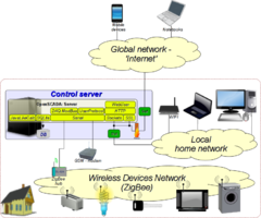
The block diagram of the house automation system is shown in Figure 1.
To control the various hardware of the house it was designed the hub and built the wireless network ZigBee of the devices for the equipment control. Overall equipment control, as well as providing the Web-based user interface and other methods of notification are made by the dedicated server of house automation. The hub if the ZigBee network is connected to the server through the RS-232 and ModBus/RTU protocol. Alarms in the automatics' control area will be sent to the user via SMS-notifications through the connected GSM-modem.
Wireless controller has the following specifications:
- the presence of the ZigBee transceiver;
- ZigBee protocol data rate of at least 200 kb/s;
- availability of USB or COM - port to connect to the server;
- power supply 220 V.
GSM-module has the following specifications (Siemens TC65):
- support of GSM-900;
- availability of USB or COM - port to connect to the server;
- support of AT standard commands of the GSM 07.05 GSM 07.07;
- power supply 220 V.
The hardware of the server:
- processor of x86_32 or x86_64 architecture (not less than Intel Core2Duo);
- 2GB DDR3 RAM;
- presence of at least three USB - ports.
As a software environment, to serve the house automation functions — "Smart House" an open SCADA-system OpenSCADA is used, in the environment of which it is designed the Web-based user interface "Smart House", and implemented the interrogation and control of devices via ZigBee concentrator.
2 Automation system
OpenSCADA has several ways of forming visualisation user interfaces, stating from integrated development tools of standard interfaces of controls the various areas of automation and ending by the low-level mechanisms of libraries and interfaces of graphic concepts.
The integrated interfaces of OpenSCADA are:
- The "UI.VCAEngine" module — visualisation engine to build a unified interfaces and presentations (final visualisation) using different types of graphical interfaces, as well as with the ability to work as a server of visualisation interface.
- The "UI.Vision" module — "UI.VCAEngine" visualiser and the GUI development interface based on the Qt library.
- The "UI.WebVision" module — "UI.VCAEngine" visualiser based on the Web-interfaces: XHTML, XML, CSS, JavaScript, DOM and AJAX.
The low-level mechanisms of constructing the user interfaces include any other graphics libraries, which have a rapid development tools of the user interface. The co-operation with OpenSCADA is produced as with data source and with the interface of the unified control of the equipment under different protocols.
In order to provide the ability of user's Web-interfaces formation directly in OpenSCADA, the module "UI.WebUser" is provided. Overall, OpenSCADA contains all the basic functions of a typical Web-server, as follows:
- Acception of the client connections over standard transport protocols: TCP, UDP, Unix, as well as over the protected connections SSL and TLS.
- Support of the basic HTTP protocol functions: GET and POST.
- Dynamic creation of the user-generated content through an internal JavaScript (JavaLikeCalc) language in the form of the flows with the contents: HTML, XHTML, XML, CSS, JavaScript languages, images of different formats, etc.
Consequently, for the construction of any user control interface it is enough to have installed OpenSCADA with the following modules: Transport.Sockets, Transport.SSL, Protocol.HTTP and UI.WebUser.
2.1 The structure and location of files
In order to reduce the load on the fully dynamic formation of the user interface, as well as to facilitate the future expansion and modification of style the Web-interface was divided into static and dynamic parts.
The static part consists of a set of template HTML-files with labels of the dynamics placement and resource files: CSS, JavaScript and images. In general, the static part is represented by files, which are described in the table below:
| File | Description |
|---|---|
| HTML-templates (HouseSpirit/Web/*) | |
| main.html | The main user interface template. Contains a general user interface with location tag of the pages' content "#####CONTEXT#####". |
| auth.html | Template of the authorisation interface with the tag of content's location "#####CONTEXT#####". It is created for using by the HTTP protocol module (/sub_Protocol/mod_HTTP). |
| access.html | Access control template. |
| temperature.html | Climate control template. |
| light.html | Lighting control template. |
| water.html | Water supply subsystem control template. |
| tech.html | Electronic and household appliances control template. |
| friend.html | User devices control template. |
| user.html | Users manager template. |
| devices.html | Device manager template. |
| loginError.html | Page of authentication error messages, or lack of it. |
| mess.html | Active alarm messages template. |
| report.html | Template for alarms', actions and system messages reports formation. |
| welcome.html | The welcome page displayed by default in the content field. |
| Resources (HouseSpirit/Web/res/*) | |
| stylesheet.css | Cascading Style Sheets of the user interface. |
| main.js | JavaScript code of the main template for the time counter and session. |
| devMon.js | JavaScript code that implements a dynamic AJAX interface for the monitoring of subsystems' device. |
| access.png, accesson.png | Images of the access control subsystem. |
| temperature.png, temperatureon.png | Images of the climate control subsystem. |
| light.png, lighton.png | Images of the lightning control subsystem. |
| water.png, wateron.png | Images of the water supply control subsystem. |
| tech.png, techon.png | Images of the electronic appliances control subsystem. |
| friend.png, friendon.png | Images of the user's devices control subsystem. |
| user.png, useron.png | Images of the users' Manager. |
| devices.png, deviceson.png | Images of the devices' manager. |
| report.png, reporton.png | Images of the alarms, actions and system messages reports formation. |
| help.png, helpon.png | Images of the help page. |
| HouseSpirit.ico | Icon of the Web-based interface. |
| hd_l.png, hd_r.png | The left and right parts of the header. |
| select_l.png, select_r.png | Background images of the selected menu item on the left and right |
| space_l.png, space_r.png | Images of the free menu item on the left and right. |
| status_l.png, status_r.png status_edge.png | Images of the status bar. |
| Report files (HouseSpirit/Web/reports/*) | |
| rep_{user}.html | The latest report of the "user" user. |
The dynamic part is implemented by the scripts in the internal language of OpenSCADA - JavaLikeCalc, which are described in the table below:
| Script address | Description |
|---|---|
| The script of the Web-site (/sub_UI/mod_WebUser/) | |
| up_hs | Main Web-site script, which performs direct reception, initial processing and forming the definitive reply, namely:
|
| Script library of the template-pages, and system processes (/sub_DAQ/mod_JavaLikeCalc/lib_web/*) | |
| user | Script of the template-page "Users Manager" implements the function of the formation of form for the users' management, depending on the rights of the logged in user. |
| devices | Script of the template-page "Devices Manager" implements the function of forming the devices' control and the alarms generation form for two types of devices: decimal and dynamic. |
| devMon | The script of the formation of the monitoring interface and form of the devices' management, configured in the "Devices Manager". This script is used by all subsystems of the devices monitoring. |
| alarms | Script of the periodical task that checks the value of variables of devices for the configured alarms. In addition to the direct formation of alarms the script provides the SMS-notification messages to users' phones, set for notification via SMS. |
| mess | Script of the template-page "Alarms" implements the function of forming the active list of alarms. |
| report | Script of the template-page "Reports" implements the function of forming the table-report with the events in the system and in the various subsystems for a specified period of time. Report is generated simultaneously on the screen and in the file that can be downloaded separately by the link. |
In general, the algorithm processing the requests to the pages is (on the example of http://localhost:10002/WebUser/temperature?script=devMon):
- request is received in the script /sub_UI/mod_WebUser/hs from the transport /sub_Transport/mod_Sockets/in_WEB_1, by means of the Protocol.HTTP protocol module;
- the template file is loaded temperature.html;
- the script of the "devMon" page is being looking for (/sub_DAQ/mod_JavaLikeCalc/lib_web/devMon). If the script argument is missing the script search is made by the name of the page (/sub_DAQ/mod_JavaLikeCalc/lib_web/temperature);
- the transfer of the page's template to the found script for the formation of dynamics is made;
- the result of the page's script execution is placed to the main template;
- if the page's script is not found, the page's template puts its contents directly into the main template.
2.2 Devices Manager
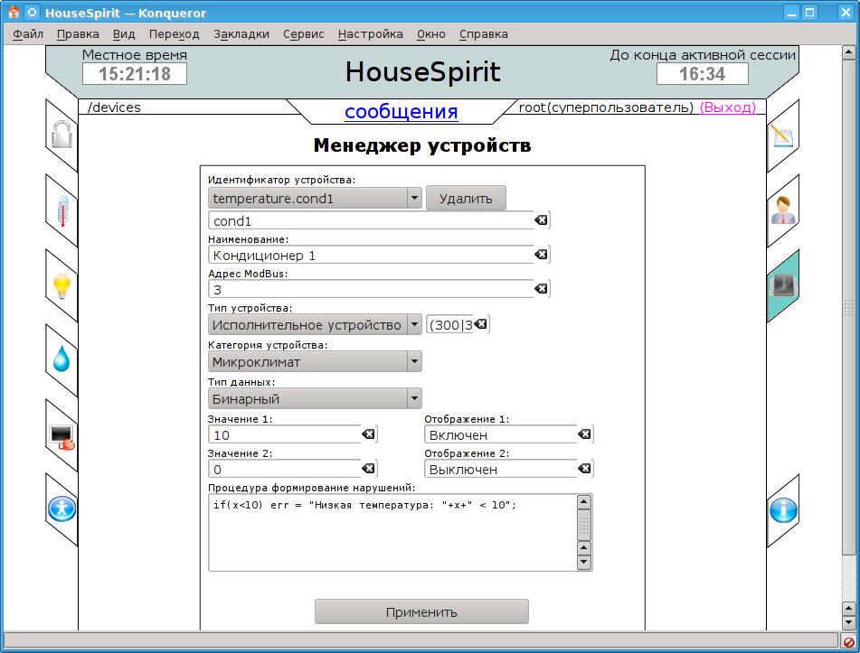
The Devices Manager is available only for root and builds the form (Fig.2) for edit, and and remove devices of two types: binary and decimal.
The created device are placed in the attributes list of the parameter of the specifically taken subsystem of "ZigBee" controller of the data source module "ModBus" (/sub_DAQ/mod_ModBus/cntr_ZegBee/). Recording format of an attribute is as follows:
- "R:0:r:cond:Airconditioning:bin:10:Enabled:0:Disabled:(120|100)" — for binary sensor:
- R — ModBus register;
- 0 — ModBus register address;
- r — read only;
- cond — ID of an attribute-sensor;
- Airconditioning — sensor's name;
- bin — sensor's type - "Binary";
- 10 — the first value;
- Enabled — the name of the first value;
- 0 — the second value;
- Disabled — the name of the second value;
- (120|100) — location coordinates ({x}|{y}) of the sensor in the scheme of premises.
- "R:3:rw:tGhost1:The temperature in the living room 1:dec:deg. С:y=2*x;:(120|100)" — for the decimal sensor:
- rw — read only;
- dec — sensor's type - "Decimal";
- deg. C — unit of the variable;
- y=2*x; — conversion formula for the received variable for display;
- (120|100) — location coordinates ({x}|{y}) of the sensor in the scheme of premises.
In addition to the direct sensors, the configuration and formation of alarms is made in the form of text procedure. The program of formation is placed in the "var" attribute of the alarms controller parameter /sub_DAQ/mod_JavaLikeCalc/cntr_alarms/prm_rules. The "var" attribute contains the following XML-tree:
<ALARMS>
<it id = "temperature.cond1">
if(x<10) err = "Low temperature: "+x+" < 10";
</it>
</ALARMS>
According to the XML-tree the formation of alarms and sending SMS-notifications to the subscribed users is made in the controller's task /sub_DAQ/mod_JavaLikeCalc/cntr_alarms, which is executed with a period of 1 minute.
SMS-notifications are sent via the serial transport /sub_Transport/mod_Serial/out_GSM and through the user's SMS-protocol (/sub_Protocol/mod_UserProtocol/up_SMS).
You can also select the delayed giving of the control action. To do this, the user sets the right time, in the form of: {Min}:{Sec}. Processing of the delayed control is made in the controller /sub_DAQ/mod_JavaLikeCalc/cntr_timers by setting the "var" attribute of the "rules" parameter with the help of requests in the XML-tree:
<TIMERS>
  <timer id="temperature.tGhost1" tm="60" user="root">20</timer>
  <timer id="temperature.cond1" tm="10" user="root">0</timer>
</TIMERS>
2.3 Subsystems
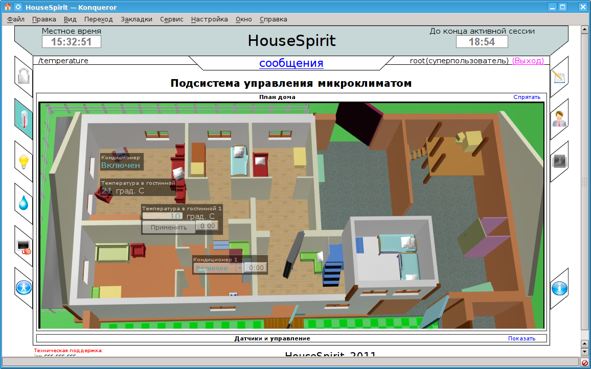
All visualisation subsystems are served by the /sub_DAQ/mod_JavaLikeCalc/lib_web/devMon script. This script process the requests from the script of the dynamic visualization of Web-browser and receive the data on the subsystem's devices, required for visualisation (Fig.3). Data about the devices are transferred in accordance with the privileges of the logged user.
The configuration of sensors is read from the parameter corresponding to the "ZigBee" controller's subsystem (/sub_DAQ/mod_ModBus/cntr_ZegBee). The values are read and written to the attributes of the sensors of these parameters or through the controller or delayed management.
The task of the "ZigBee" controller is executed with the period of 1 second, in the process of which the request of the the current values of all configured sensors is made. Record of the the values is made on the fact of modification, regardless of the periodic polling task or through the delayed management controller in the case of installation of nonzero timer.
Connection to the "ZigBee" controller is made via serial outgoing transport /sub_Transport/mod_Serial/out_ZegBee.
2.4 Users manager
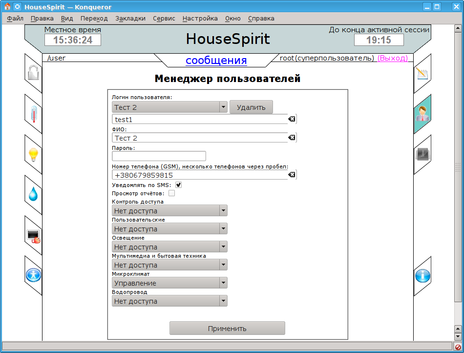
Users manager (Fig.4) is intended to create, delete and edit accounts of ordinary users.
Users are divided into administrators and ordinary users. Identification of the user as an administrator in OpenSCADA is made by turning it into the "WebRoot" group (/sub_Security/grp_WebRoot). An ordinary user is included into the "Web" group (/sub_Security/grp_Web).
In OpenSCADA, each user (/sub_Security/usr_test1/) has a text description field, which in this case serves to store its special settings in the following way:
TEL: +380679859815
SMS: true
Report: false
sub_access: --
sub_friend: --
sub_light: --
sub_tech: --
sub_temperature: rw
sub_water: --
In the case of an administrator's account the records of an access rights to the subsystems are not available, but there are system-wide settings such as the lifetime of the session (/sub_Protocol/mod_HTTP).
2.5 Messages
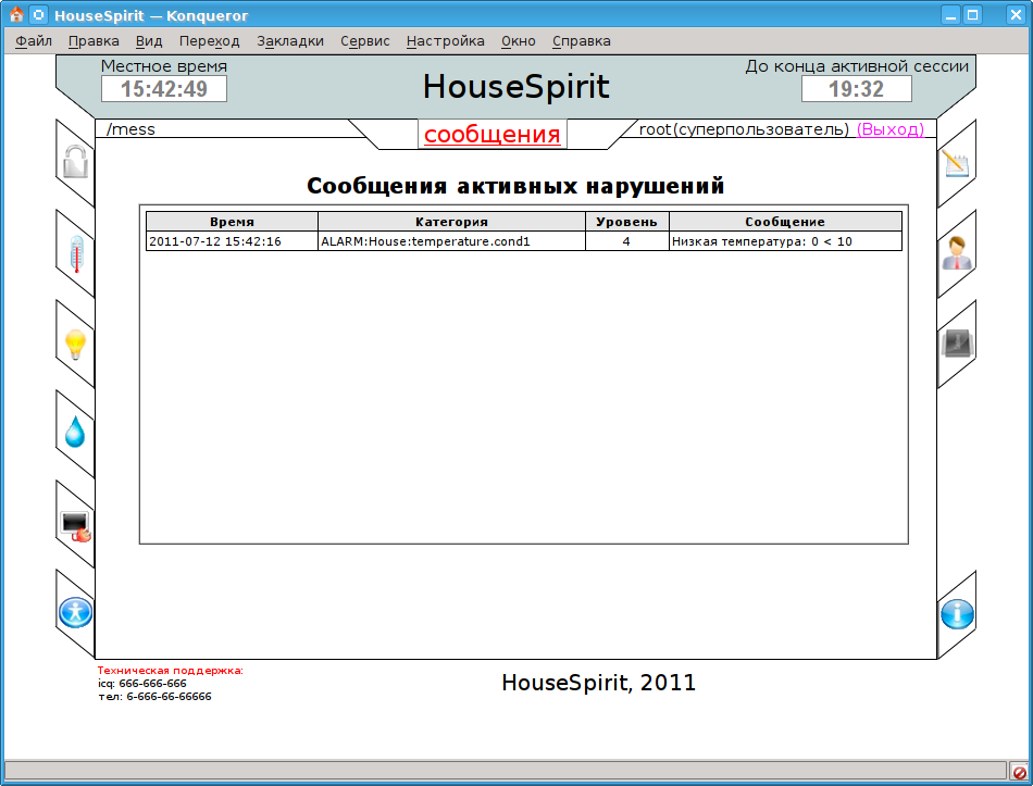
The message list is formed based on the active list of alarms in their categories "ALARM:House:*" in tabular form, with the time, category, level and the alarm message (Fig.5).
2.6 Reports
During the report's generating the time range is indicated and messages' types are select. The generation of message for the following types is provided:
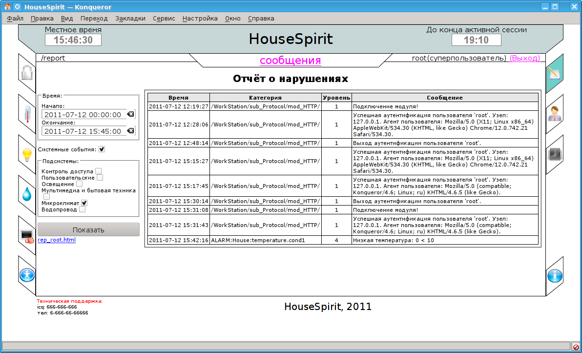
- "System events" — includes messages about login and logout users on the resource by means of the massages category "/\/sub_Protocol\/mod_HTTP\//".
- "Monitoring and management subsystems' events" — includes alarms and record the new values of the sensors through the categories of messages "/(ALARM|SET)\:House\/:".
The protocol is formed as a table (Fig.6) with the time, category, level and message of the alarm, which is also recorded in the separate report file, later available on the link to the separate opening.

